 In the last article,
 we talked about the composition of the electric transmission of a mining truck, and in this one I will tell you about how we put it into operation at the plant and what problems we encountered. From this article you will learn: how to test an electric motor weighing a half tons, how to heat the air with a megawatt capacity and how many boards need to be thrown out to make one.
Test bench layout
Before putting the equipment on the dump truck, it must be tested. But how? If it is wasteful, the test bench can be several times more expensive than the transmission itself, and if you test the equipment with insufficient quality, then you will not sit in a career with oscilloscopes.
Since there are two traction engines at the dump truck, the most convenient scheme is to test the engine on the engine:
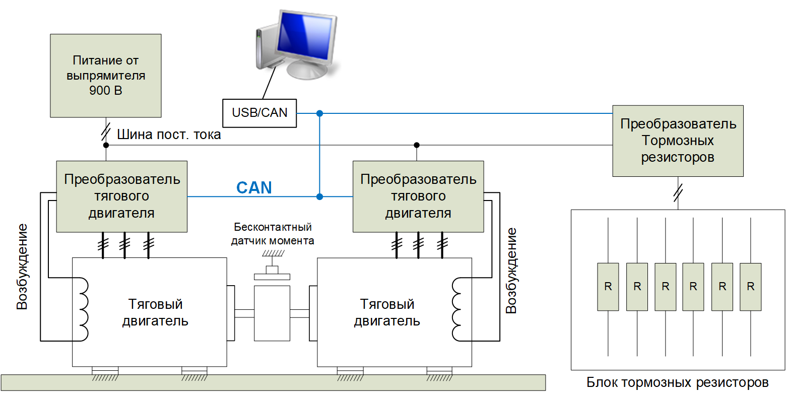
At the manufacturing plant, the motors are coupled together through a rotating non-contact torque sensor, and are controlled from a standard converter (power control cabinet). At the same time, during testing, one engine works as an engine, and the other as a generator (recovers energy, works in brake mode). The power converters of these motors are connected via the DC bus, which means that the recovered energy of the engine operating in the generator mode returns back to the DC bus and goes to the engine converter.
Such a cycle of energy is obtained, and such a system differs from the perpetual engine only that it is additionally fed from the network, but the value of this consumed energy is only the total losses in both drives. So, in our case, when two engines with a capacity of 320 kW from the network are consumed, only 80 kW are consumed.
Also in the picture you can see the converter brake resistors and the resistors themselves: they are not mandatory, but highly desirable as protection. The fact is that during debugging, abnormal modes of operation and emergency shutdowns, voltage drops in the DC bus are possible. In this case, the brake resistor converter sits on guard and drains energy if the bus voltage exceeds a predetermined threshold (for example, 1000V). Otherwise, the transistors will break through and everything will explode.
In addition, the braking resistor is useful in case of a need to abruptly stop the drive. If the drive rotates, then without a braking resistor there is no way to quickly stop it - just coasting out by inertia, since there is no place to put regenerative energy. With a resistor, in which case you can brake in a couple of seconds.
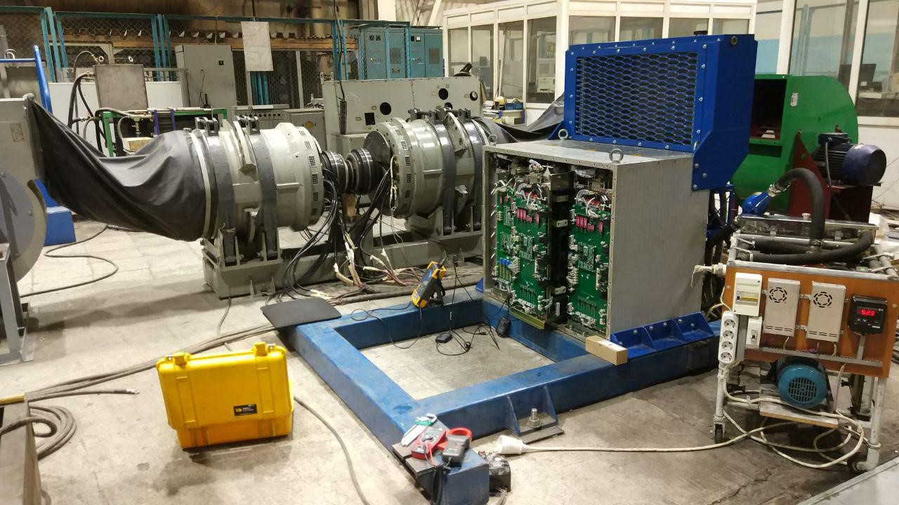
This is how this stand looks like in reality at PTFC ZTEO:
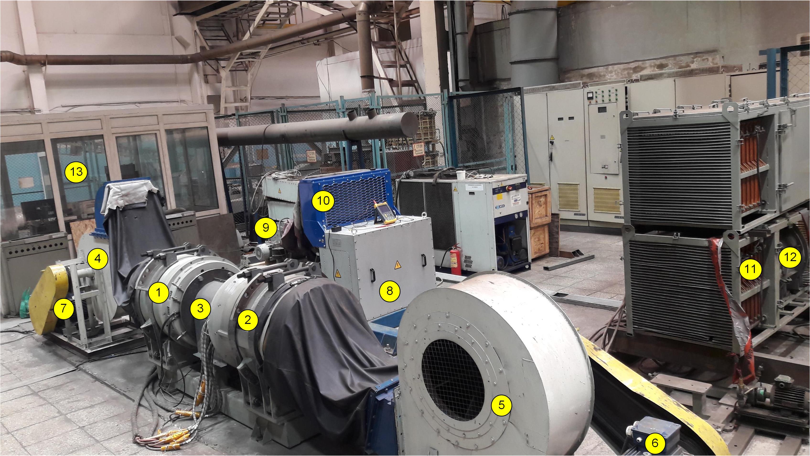
What is here that:
1,2 - tested traction motors. They are smoothed through a torque sensor, covered by a casing 3.
Since air-cooled in the dump truck (from a large fan on a diesel engine), centrifugal fans 4.5 are used to simulate it on the stand, which rotate through a belt drive from 6.7 asynchronous motors.
A similar fan 9 blows through the radiator 10, which, through the cooling water circuit, removes heat from the converters of the control cabinet 8.
At number 11 you can see the section of the braking resistor, and then behind it stands its fan 12.
In the booth 13 (its local name is an aquarium) it is supposed to sit during the tests, there is a computer for controlling the drives via CAN, as well as buttons for supplying and regulating the power voltage. The remaining cabinets and devices do not have any relation to this test.
Here is another video of the same stand during his work:
Fans create the most noise here, and the traction motors themselves are hardly audible. And here is the aquarium from the inside:

How are the tests
What and how are they tested on the stand? Generally speaking, the final goal of the test is to remove the traction characteristic, as well as conduct thermal tests. Traction characteristics are the points of the required torque from the rotational speed. For a given traction engine with a power of 320 kW, it is approximately like this:
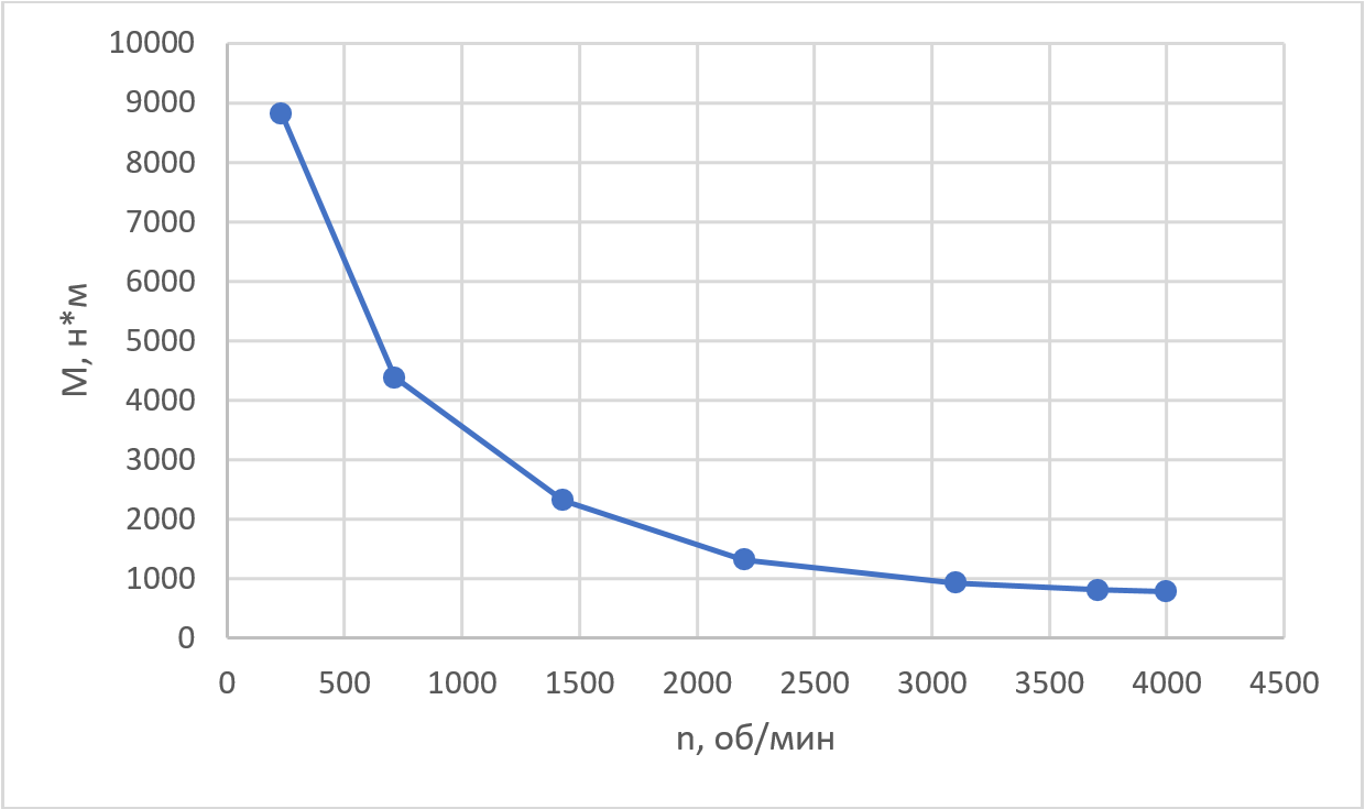
The characteristic requires operation with a constant power of 320 kW in the range from 390 to 4000 rpm. This is quite difficult to achieve, see the reasoning at the end of
this article .
Such a characteristic is removed during the first tests in a fully manual mode. One drive is started in the mode of maintaining the rotational speed (with the PI speed controller), and then the second drive in the mode of maintaining the torque sequentially increases the torque reference until the torque sensor shows the required torque. After that, all available instrument readings are entered in the table. Usually these are all voltages, currents, moments, current consumed from the network, cosine phi, etc. And so pass on all speeds.
A lot of information is also removed not by external devices, but by means of a converter, for example, the controller calculates cosine phi, the averaged stator current is derived along the d, q axes (vector control axes), the voltages along these axes, etc. If desired, oscillograms of instantaneous values are also taken, for example, phase currents, the work of the rotor shaft position sensor, the work of the pathogen, etc .:
Using such oscillograms with the “eyes of the control system”, one can understand why and where something goes wrong, if the drive does not give out what is expected of it. I already wrote more about debugging software in the drive in
this article , and everything said there is completely true here.
The second step is the heat test. Drives are put into operation at a nominal point and spin for several hours until all temperatures, both the motor and the converter, reach the steady-state level. If all temperatures are within acceptable limits and correspond to the calculated ones, then the heating test is considered as passed.
Since it is not possible to install temperature sensors everywhere, heat indicators are used to measure the temperature of individual parts - before testing for heat in the power cabinet and on some elements of the engine, special stickers are glued to the places of interest, which change color with increasing temperature. After testing, all indicators are checked and recorded:

See this round indicator on the microcontroller? A blackening in place of 71 degrees means that this temperature has been exceeded, but a 77 white circle indicates that 77 degrees has not been reached here. And the neighboring thermal indicator on the base plate shows that even 60 degrees have not been reached there. Usually, any new block design is pasted over with such indicators - power buses, different parts of the radiator, different parts of the board, etc. Later, during serial production and operation, it is possible to dispense with readings of standard temperature sensors: in our unit such sensors stand on each IGBT transistor, radiator, the air temperature is measured separately, and 6 more temperatures come from the traction motor.
In addition to the tests at the nominal point, tests for work in the overload mode (with a maximum torque for a limited time) and work with exceeding the maximum speed are also carried out. Then the roles (who is the engine, who is the generator) are swapped and everything is repeated.
With the release of serial products such tests can be automated to some extent, for example, to provide automatic removal of the traction characteristics with the formation of the protocol, but this is done only with very, very large production volumes.
But this is about engines. There are two more components of electric transmission - generator and brake resistors. They come with them too easy. The generator, instead of a diesel engine, is connected to the engine drive - a special machine for testing, usually much more power.
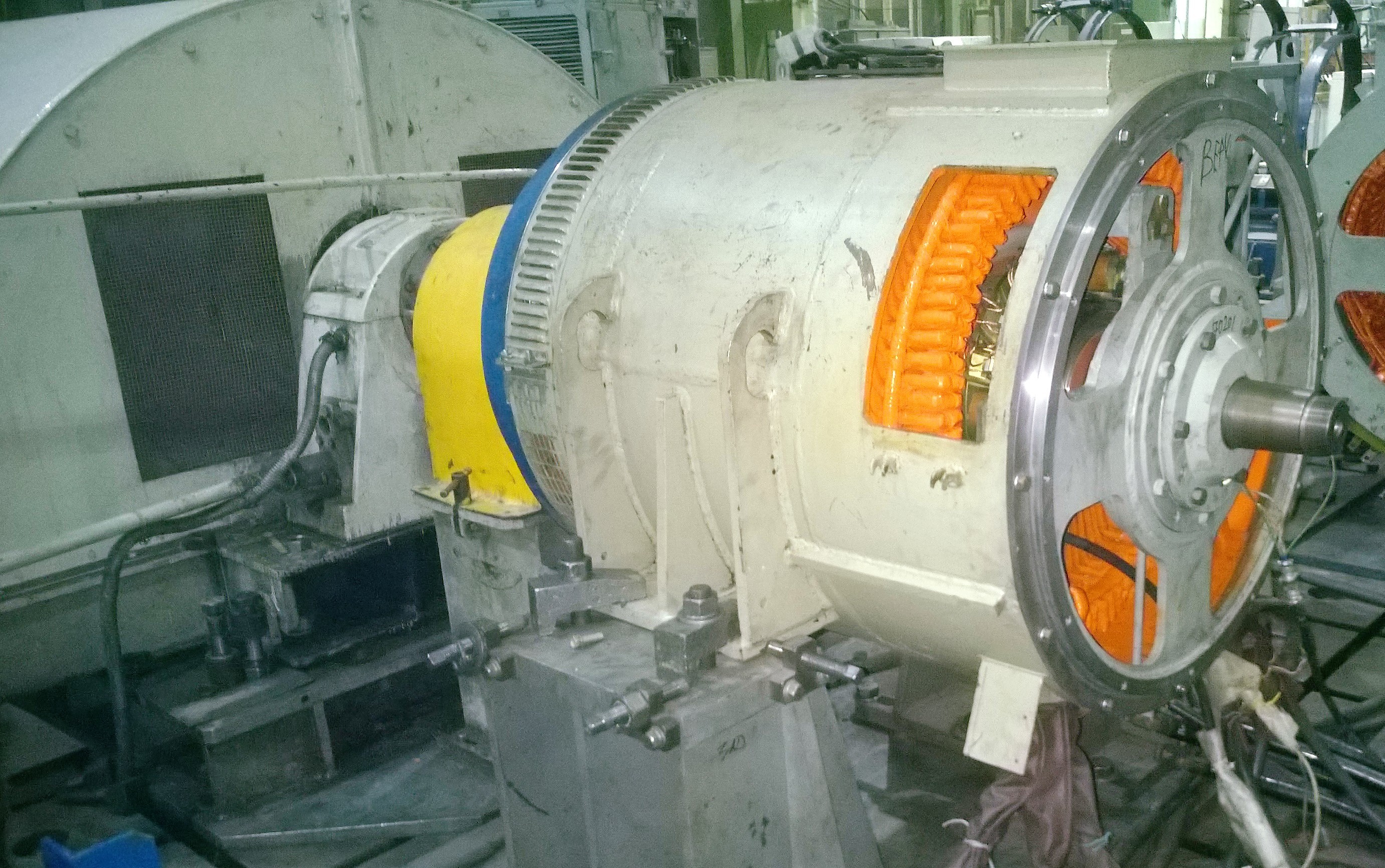
In the photo in the foreground there is a small test generator, and in the back half-side it is a powerful drive motor, slightly drowned in the floor. Also a synchronous machine, by the way.
The output of the generator is connected to the rectifier (preferably to the staff from the power cabinet), and the rectified voltage to the brake resistor. And they drive it all up to the established temperature.
Unlike engine tests, where only the power of the losses was consumed from the enterprise network, the full power of the generator is consumed in this test, i.e. 800kW, and all this is blown into the brake resistors, i.e. goes to the air heating in the shop. It is not so much a big problem in the winter ... but in the summer after an hour of such tests in the workshop it becomes +40 and higher. And electricity is also burned a lot. Although compared with the price of the tested equipment - a penny.
How are the tests actually
Unfortunately, everything described above is the test of the ideal universe. In fact, everything happens differently. If we are talking about the first copy of the new equipment, then at first nothing works at all, even if you, as a company, have eaten a dog on such developments. Problems float everywhere, ranging from errors in PCB layout to the very concept of engine control.
So, for example, the controller usually undergoes 2-4 iterations of the PCB layout before it gets rid of obvious errors, non-plug-in connectors, interference on a pair of three ADC channels and so on. First, each board is tested on the table, manually, the power supply is checked, a simulated external signal is sent to the board's test nodes, its processing by the board is checked with a multimeter or oscilloscope. And as a result, the very first version of the board after a full check abounds in approximately such modifications, after all:

Usually, after the surgical corrections shown, the board works, but it is absolutely not suitable for installation on an object. Maximum for laboratory testing.
We used our ready-made and time-tested controllers in this project, so there were no special problems with these boards. However, the base boards of the converter, into which the controllers are inserted, as well as the design of the power cabinet itself were developed for this task from scratch. Therefore, the base boards have undergone 3 or 4 iterations before they hit the dump truck.
It is difficult to make a mess in the electrical circuit of the power cabinet, since there are relatively few details (although it happened that the power diodes were installed by the wrong side). There are some other problems with the cabinet and transducers: assembly (something does not fit in or out of the screwdriver to screw it up), the influence of some conductors on others (interference, interference and this is all), overheating of some parts.
For example, in this project there was a problem with the poor performance of the snubber transistors. Snubbers are such a node, usually a capacitor and a resistor, which is placed next to the power transistor and must reduce the switching overvoltage when the power transistor switches. So, snubber in this unit worked and overvoltage reduced, but the current through snubber capacitors was so large that the capacitors degraded and eventually exploded. I had to recycle the layout of the transistors and power buses to eliminate the problem.
But we had a conceptual biggest and most unexpected faacap here. Initially, when we learned from the designers of electrical machines that the traction motor would be 9 phase with three independent triads, we decided that it was easiest to install three independent controllers and control each triad separately, as if it were a separate three-phase electrical machine. Since the rotor position sensor is unified and wound up in all three controllers, we expected that the control will be synchronized from the point of view of the magnetic flux of the machine formed by the windings, and there is no need for more. There is sound grain in this approach, and in some projects we did it
successfully , but it didn’t work here.
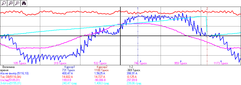
When we started to make the first switch-ons at the plant, it turned out that each triad with its controller works separately, but switching on several motor triads simultaneously led to strong unexpected current ripples in each of the triads. Here, the left picture shows (yellow and red) the shape of the sinusoidal currents of the phases of the first triad when this one triad operates, and on the right these currents, if you jointly include the neighboring triad:

Ripple current 50% amplitude of the first harmonic!
It turned out that the inductive coupling between the windings of different triads is large enough that the current pulsations from the PWM operation of one triad could be transformed into another triad as a kind of parasitic switching EMF, and thus spoil the shape of the phase currents!
There was only one way out in such a situation - to fully synchronize the opening and closing of transistors in neighboring triads, so that the transformer EMF from PWM was of the same sign and mutually compensated. But how to do it if there are three controllers, and the PWM frequency needs to be changed while the drive is running? Quartz oscillators on different controllers are slightly different, which means that even if you set the PWM frequency to be the same, all registers are programmed in the same way and the controllers are started exactly at the same time, the PWM timers phase will “go off” with time. Nor was there any software synchronization of speech, the program simply would not have time to measure and correct such small time intervals directly, and the controllers used for synchronization of PWM did not assume. After all, the PWM frequency is up to 10 kHz, and it is necessary to synchronize the phase of the PWM timer with an accuracy of a fraction of the period.
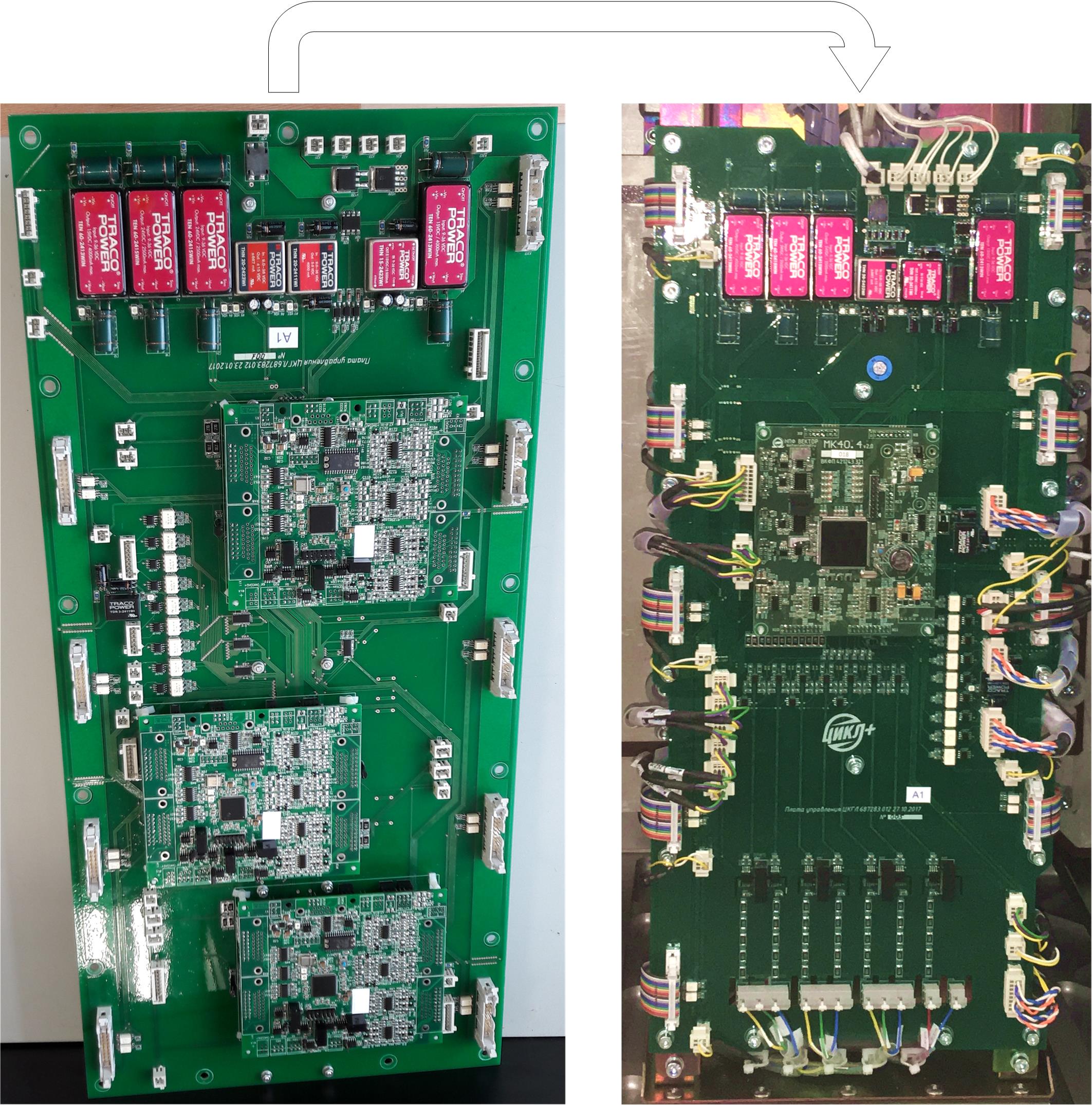
The right decision here was to transfer control to one controller that would control all the triads at once. So it was done as a result, as indicated in the previous article - the domestic microcontroller with 18 WIMs caught in time, we were just at the time mastering it in another similar project.
Because of this, in the near future, we had to rework the baseboard to replace three controllers with one, and also to rewrite all the software for a new microcontroller, to develop a multi-phase PWM software module, etc. This strongly threw us back in time for the delivery of the project.
Of course, looking back, we can say that the problem was obvious - the windings wound in some steel grooves of course have a strong inductive connection, and the fact that such a problem takes place shows any calculation on a napkin at dinner. However, at that time it did not occur to anyone - especially because we had previously made another machine (with less inductive connections) using the same method of several controllers and everything was fine.
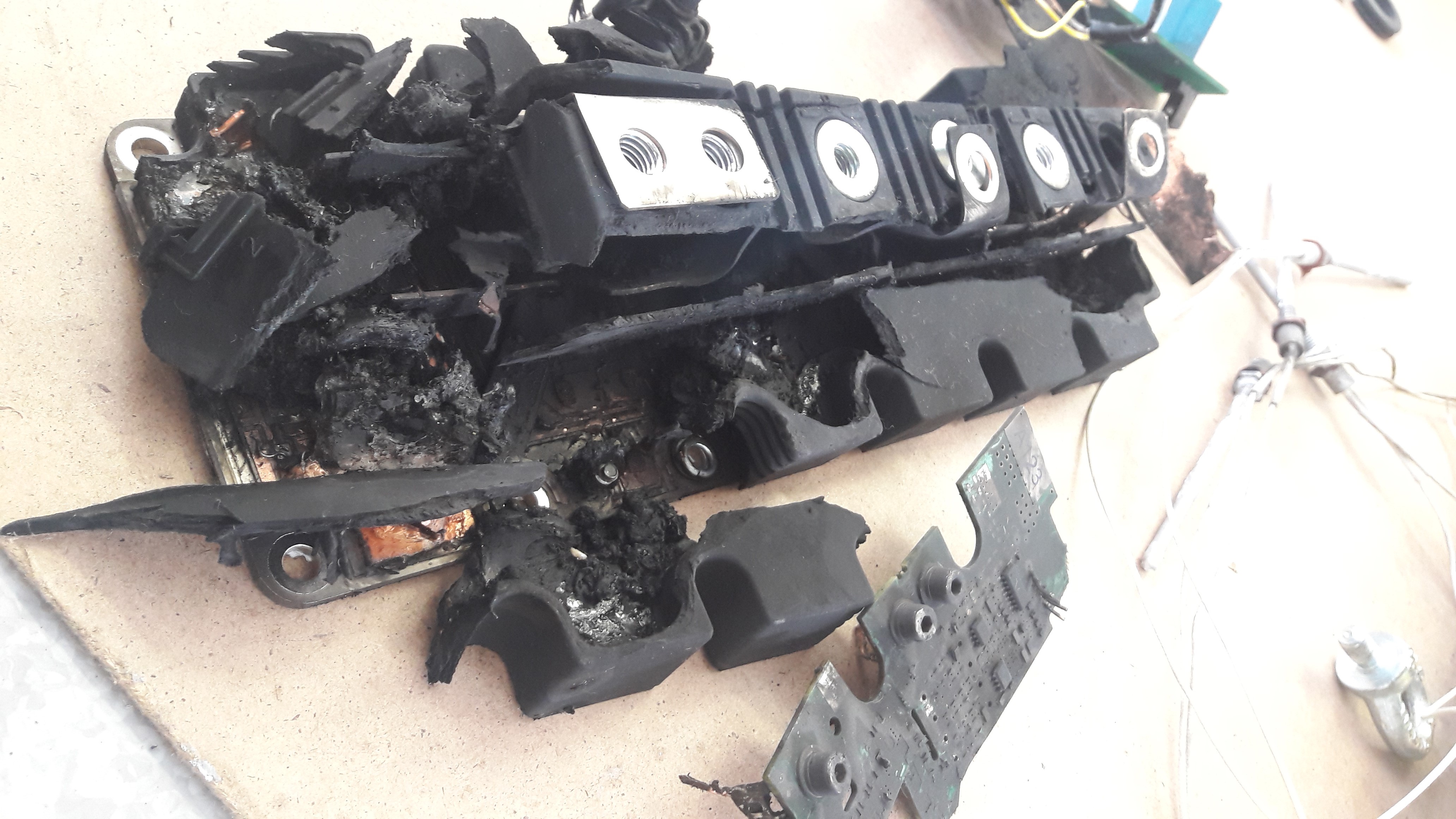
The problems can be described for a long time - I’ll omit how the controllers for the realities of the hardware rewrite in a fast pace, as in tests, transistors inevitably explode and have to be cleaned of soot and sort through the entire power cabinet, as in an electric motor pulls out the fasteners of the magnetic circuit and grinds all the windings and etc. All this happens, in each project a little differently, but always a lot.
This is a normal development process. If someone promises you that they will now take and make a working sample of a complex electrical device in one iteration - do not believe this is not an indicator of the executor of experience, but, on the contrary, an indicator of its absence. You can not do well right away. Any new development is an iterative process of trial and error. And for the worker of the first sample, it is necessary to lay at least two times, and preferably three times the number of components - because some equipment will explode, and some will have to be thrown away as an unsuccessful solution.
Additional tests
Also, the article does not describe many of the autonomous tests that precede the drive tests in the collection:
- Thermal chamber tests - low temperatures, high humidity, condensate, and that’s all;
- Tests for checking IP (moisture and dust);
- Tests on a vibrostand - whether something mechanically will fall off; (by the way, if you do life tests for vibration, then the sample of equipment that passed the shaking cycle is not suitable - its mechanical resource is developed, suitable only for the laboratory, if it remains alive)
- Insulation strength tests - high voltage is applied between the housing and the conductors, it is verified that the insulation is good;
- Tests for protection against short circuits (the equipment must shut down and not bang);
- Tests of electric machines for vibration (i.e., the vibration level is measured at different rotational frequencies: axial, radial, etc.).
With all these tests, there is also a big risk of disabling equipment or bringing it to a “non-delivery” type. This is a word about the triple reserve of iron for development. However, some tests are done once for one design, and some are repeated for each instance during mass production. It depends on the cost of the tests themselves and the degree of damage to their equipment. For example, vibration tests and short-circuit tests are not exactly carried out on each specimen, since they reduce its life.
Conclusion
But all these tests and checks are only half of the entire commissioning. Even ideally working in the laboratory, new equipment will not work out of the box at the facility. Again, you will have to refine something, add software and encounter unexpected problems. How we launched and commissioned the dump truck itself - read
the following article .
Some advertising
Almost all the staff of the firm "NPF VECTOR" are graduates of the department of automated electric drive of NRU MEI. The department of AEL is the most important partner in the development of such projects. We remind that NRU MEI continues admission to the magistracy in the direction of "electric power industry and electrical engineering", including the program "electric drive and automation". With the rules of admission can be found on the website of the
admission committee of MEI .
The page of the Department of AEP on the portal of NRU MEI. The official
website of the department .
Finally, make a riddle
What is it and where is it standing?

Correct answerThis is the excitation winding of the traction motor. It stands between the two halves of the rotor of a valve-inductor motor with independent excitation. It is schematically shown in
this article , where the HB is considered.