Probably everyone knows that big mining dump trucks have an electromechanical transmission (since 1968): ICE rotates a generator, the energy from which drives the traction motors in the rear wheels of the dump truck. On the Internet you can find a lot of review articles and "test drives" of these machines, but many technical details are usually omitted. This series of articles will be written from the wrong side, on behalf of the developers of the electric transmission: how we developed it, on which controllers, on which engines, how we debugged and started the car. We are also ready to answer your questions in the comments. Interesting? Welcome under cat.
Why electric?
We were engaged in a machine with a carrying capacity of 90 tons. Far from the biggest (there are 450 tons), but not the smallest (there are 30 tons). Why do such dump trucks do with electromechanical transmission, and not with hydromechanical transmission? It turns out that with increasing power, it is becoming more and more difficult to make mechanics and hydraulics so that it is reliable, simple and with good efficiency. There are layout problems.
In addition, with increasing mass, the problem of brakes becomes more acute. In an electric transmission, it is very easy to dissipate braking energy into brake resistors and blow heat off with fans. If on such a dump truck to brake with mechanical brakes, the brakes will be enough for 500 meters. And since the machines work in quarries with long descents, the problem of braking is very acute in them. Thus, the electrician (as I will briefly call the electromechanical transmission) "at the same time" also solves the problem with the brakes.
The mass of 90 tons is somewhat transitional - some manufacturers still make cars of this mass on hydraulic transmissions, and some, such as BelAZ, are already on electric ones. Even more weight is definitely for the electrician, while smaller machines are for the mechanics (hydraulics).
Everything has been invented before us and has been working for a long time. Why do more?
BelAZ - (Belarusian Automobile Plant) produces dump trucks, but it often purchases components such as diesel and electric transmission from other organizations. It is beneficial for BelAZ to have several equipment suppliers in order to stimulate competition, try new design solutions and have insurance in case of a supply failure of one of the manufacturers.
Now electric transmissions for BelAZs are already being manufactured by many companies, such as Siemens (Germany), General Motors (USA), Electrosila plant of Power Machines OJSC (Russia), manufacturers such as ALC “STRIM” (Belarus) try their hand, Rouselprom (Russia) and ... "we."
We are an association of several companies in this project under the leadership of
CJSC PTFC ZTEO - a transport equipment factory located in Naberezhnye Chelny. At this plant, electric motors and a generator for our transmission are manufactured and tested, power converters and software are made by the Moscow firms
NPP CYCL + and
NPF VECTOR , and the design of traction motors is done at the University
MEI .
Since we have experience in the development of electric transmissions for other vehicles, it was decided and arrangements were made to make an electric transmission for BelAZ. Arrangements with the manufacturer of dump trucks were simple: to make your transmission on one machine. If she goes and does not break in operation, they will buy more from us. If not, they will not even pay for the development and manufacture of this equipment. We decided what to do.
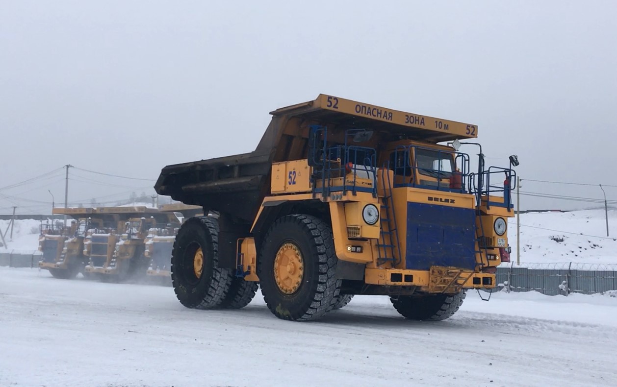
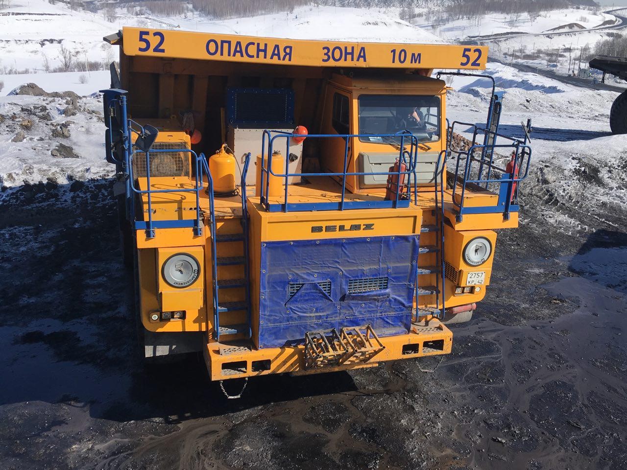
Thus was born the dump truck with our set of electrical equipment (). In this case, the first version of our equipment was installed on the used dump truck as part of its overhaul. The old electric transmission was removed from him "for parts", and our new one was installed there. All the replacement and wiring, docking to the existing equipment of the dump truck and finishing the software under the nuances of a particular machine is at the expense of the contractor.
How does the electromechanical transmission BelAZ
First, a little bit of terminology. Is it possible to consider such a dump truck a hybrid? He also has a diesel and electric motors. So, according to
Wikipedia , a hybrid car is a car that uses more than one energy source to drive the drive wheels. In this case, the source of energy is one, ICE, and formally this machine is not a hybrid.
On the other hand, the
English-language Wikipedia says that hybrids are diesel trains and submarines, which use the same scheme with a diesel engine that rotates a generator. However, the train can be powered, in addition to diesel, from an external source of energy (contact wire), and then it formally turns out two sources of energy. And in the submarine there is a battery.
Therefore, it is proposed not to go into the search for deep meaning in relation to this terminology and move on.
If we forget that there is no battery in this dump truck, then the scheme of the electromechanical transmission corresponds to a sequential hybrid: the internal combustion engine rotates the generator, and then the energy is transmitted electrically. And there are parallel hybrids, where there is both a mechanical path of energy transfer to the wheels and an electric one (for example, the Toyota Prius, Lexus RX450h and others).
A sequential hybrid is easier to do, since the mechanics are eliminated, but the “vitality” of the machine is theoretically reduced, since there is no “backup” flow of energy transfer in case of a single failure. Although the last point is controversial, for a serial hybrid is so much easier to parallel that a significant reduction in the number of parts and the elimination of complex assemblies makes such machines very reliable.
The structure of electric transmissions for mining trucks are different. Historically, they were based on DC motors, and, oddly enough, this type of transmission is still being
produced . However, in recent decades there has been a massive transition to AC motors with frequency converters due to the greater final reliability and the absence of the need to maintain the engine manifold. Thus, the typical structure of alternating current electric traction of such a dump truck can be represented as follows:
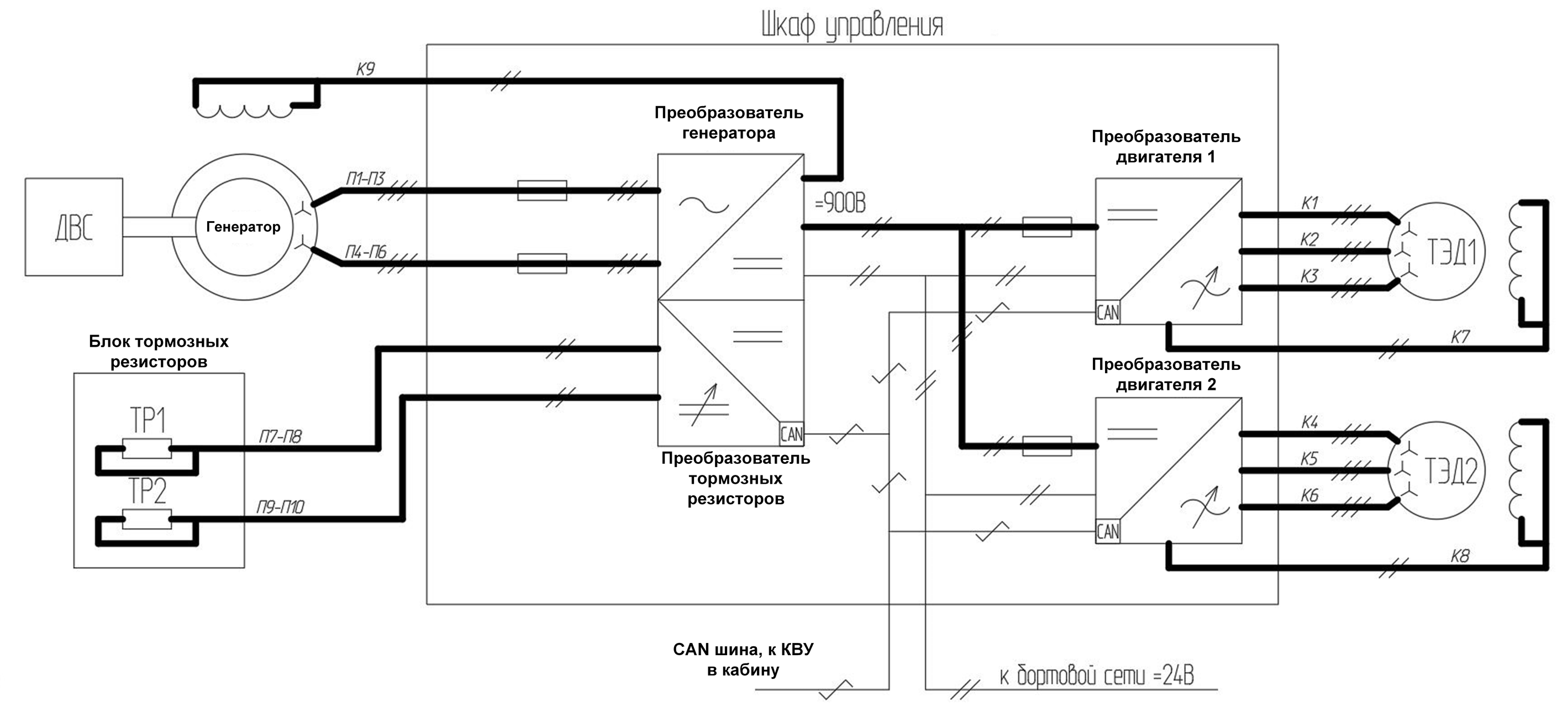
ICE rotates a generator that produces electricity. The generator is usually either based on a synchronous or asynchronous machine (for more details on the types of electric machines, see
this article ). After the generator there is a converter, which makes a constant from the alternating current of the generator.
If the generator is synchronous, then the converter is a regular rectifier (more often, a multi-phase generator and a rectifier are made to reduce the ripple of the rectified voltage). Also in such a converter there is a control unit of the exciter, which regulates the current in the excitation winding of the generator and thereby adjusts to different rotational speeds of the internal combustion engine and the output power. In fact, such a pathogen is a half bridge of IGBT transistors with a control system. I must also say that there are generators with permanent magnets, in which there is no excitation winding, but they are usually unjustifiably expensive for such capacities and sizes.
If the generator is made on the basis of an asynchronous machine, then the converter is much more complicated, namely it consists of a full-fledged inverter and works in vector control mode (read vector and
two articles about vector control).
After the generator converter, the energy is fed to the DC bus. The capacity of the internal combustion engine of a dump truck weighing 90 tons is 700-800 kW, and for this value at the current level of development of IGBT transistors the voltage of the order of 800-1000V on the DC bus is optimal. With a lower voltage, the currents are too high (and the more the current - the thicker the wires, the heating and losses), and with a higher voltage, the transistors become too expensive and slow in terms of switching frequency.
The constant voltage is then supplied to the converters of the traction electric motors (TED), which are inverters, the same as those used in conventional frequency converters. The design features of the transducers are directly dependent on the type of traction motor used. There are also many options: asynchronous motor, synchronous, valve-inductor (of different types). For more on understanding the difference between engines, refer again to
this article .
We used a valve-inductor motor with independent excitation in this project. Mainly because with these machines we have more accumulated experience, design "hurt" and written software. In addition, this type of engine tolerates overload torque as compared with asynchronous, which is important for mining equipment. Structurally, the engines are installed directly in the rear wheels of the truck, where they are also joined by a wheel reducer.
The block of brake resistors is used to dissipate the braking energy of the machine into heat. Since the power “drained” into heat also needs to be regulated, there is an appropriate converter in front of the brake resistors. It is usually made according to the simplest scheme in the form of one transistor rack for each plug-in resistor, where the power dissipated in the resistor is controlled by the PWM duty cycle of this transistor. Due to the convenience of layout and safety on the machine 90 tons, two separate channels are made for resistors.
Of course, all at once the question arises, why not put the battery and not accumulate braking energy, and then use it? Good question. From the point of view of energy conversion, there is no problem. But in our realities, batteries for such power are very expensive, delicate (the operating temperatures of BelAZ from -50, it is necessary to solve the issue with heating). And in the career of the car business - it is a consumable item, the main thing is to fulfill the plan and not stop the mining process. Reliability, simplicity and maintainability of the machine are put forward fuel efficiency.
In addition, usually, a loaded car goes up in a quarry, and the empty one goes back down, so the energy expended to ascend is much more than dissipated into resistors during descent, there is not much to recoup there (taking into account the efficiency of the drive). Even economical Europeans are
just trying to replace diesel with batteries in such cars.
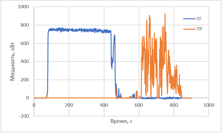
However, let's calculateWe have logs of real operation of a dump truck in a quarry. Let's take one car up and down and calculate the energy that the generator produces (ie diesel), and which is dissipated in brake resistors. One walk in movement takes 10 minutes, including lifting, unloading and descending. Well, then 5 minutes more waiting for the queue at the excavator and loading. In the logs it looks like this:
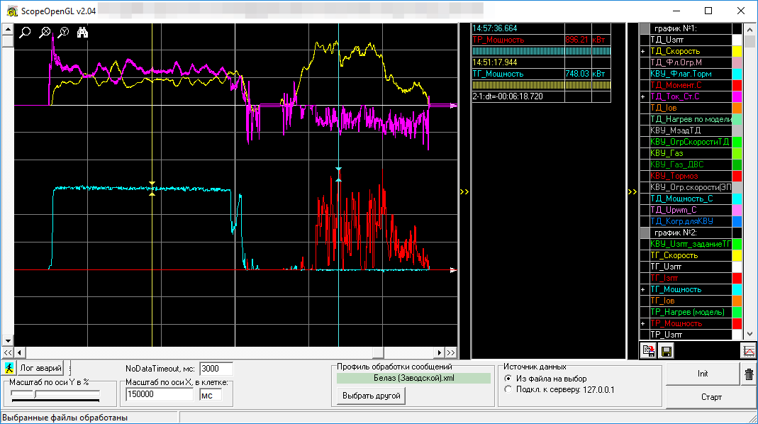
Here, on the upper graph, rotational speeds and currents of traction motors (yellow and purple, respectively), and on the lower generator power and brake resistors (blue and red). Let's save the log in the form of points and build the same thing in Excel:
Now we integrate over time to get energy:
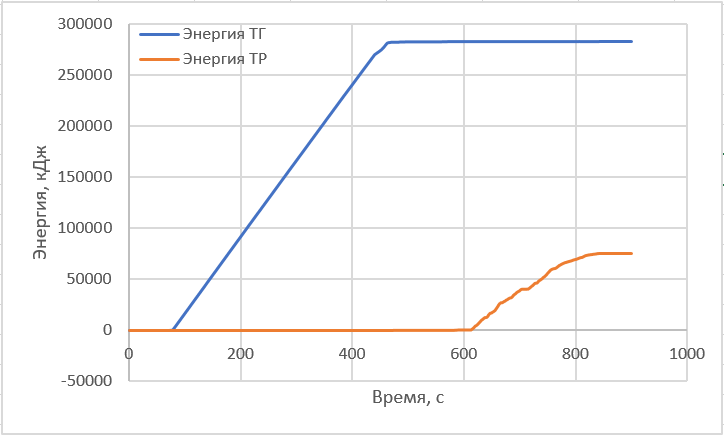
We received that 280 MJ of energy is spent on a walk, and it dissipates in resistors on a 75 MJ descent. Yes, a quarter of the energy could be saved by recuperation.
Let's estimate the battery to bend the BelAZ and keep this energy on the way down. Tesla has a battery of 85 kWh, which is 306MJ of energy. This is quite enough for a four times longer descent (but I must say that our quarry was very small, and generally speaking there are those where the cars go half an hour or even more). Only here, the battery charge current will not work - as can be seen from the power graph, you need to charge it with a peak power of megawatts (in places), or with an average descent power of 250 kW (if somehow this is ensured by uniform braking). If you do not deal with the obvious killing of the battery and charge it with a current of no more than 1C (
I took the approximate composition of the battery
from here ), then for accepting a power of 250 kW you need 6-8 such batteries, i.e. 510kW * h, which gives the mass of batteries something like 3 tons. For a 90-ton truck, there’s not really a lot.
Although you can practice speculation in this place and say that Tesla Supercharger charges 120kW batteries and nothing, and it seems like they are going to increase power. Yes, and Tesla itself slows down with great power (albeit a very short time). In this case, maybe one Tesla battery is enough, and nothing there is so violently degraded by a large charge current (I am not a specialist in battery chemistry). In addition, when charging with a current of, say, 3C, the battery already has a markedly low efficiency, and quite often what we can save in recovery, goes into heating the battery, cooling issues will arise. But the fact that the batteries still need more, shows the next paragraph.
Let's calculate the battery life time. Drivers say that they have about 20 walkers per shift, and since the machine is working around the clock, let's take 60 walkers per day. This is 60 * 75MJ of energy pumped back and forth from the battery, or about 0.4 charge / discharge cycles for six batteries per day. If you take the
battery life time scenario of 500 cycles, then this is just under three years of operation and the battery can be thrown away. One Tesla battery
costs more than a million rubles , and we are going to deliver such 6.
It remains to calculate the cost of solarium, which is burned for nothing. Although the diesel controller also sends instant fuel consumption in its CAN data, and it can also be integrated, but I don’t really believe this data and suggest using specific indicators. It follows from
this article that 200 grams of fuel is spent on the production of one kilowatt-hour of electricity. We spend 60 * 75MJ "per blow in resistors" per day. However, do not rush to multiply: not all this energy can be saved.
The efficiency of a lithium battery with charge / discharge currents of 1C is about 0.8-0.9 (a larger value for LiFePO4), the converter efficiency is also about 0.95, which means it’s good if we have 60 * 75 * 0.9 * 0.95 * 0.95 = 3655 MJ of energy spend the equivalent burning solarium. The efficiency of the bidirectional DCDC converter (which converts the energy from the car's jumping kilovolt bus to the battery and back) I put two times, because they need to be charged first and then the battery is discharged. Now multiply: 3655 * 0.2 / (60 * 60) * 1000 = 203 kilograms of fuel, or 240 liters, or 11 tr. per day on the warm wind of the resistors. For three years, this is 12 million. at the price of batteries somewhere 7 million
Also, the cost of the batteries still needs to be added to their maintenance and replacement of faulty cells (idle time for this machine), you need a charging converter (also a million, probably). It is also not a fact that in winter the batteries will be delighted with the charging current 1C, they will need to be somehow heated or limited by the charging current, and in the summer they will also be well cooled.
In addition, the losses from the underload of the car for these 3 tons of battery weight and the energy for their transportation up and down are not calculated.
The advantages of the batteries include the fact that when lifting, they will send power to the wheels, thereby increasing the productivity of the machine.
In general, there seems to be some benefit from the battery by the calculation, but not so striking as to run them immediately. It all depends on the number of cycles that they live in these conditions, and nobody knows for sure.
You can still remember about supercapacitors. But with them, something really turns out badly. I took the
first from the more or less modern. One assembly 125V 63F, 60kg, 600 tr. We need for one short descent of such 75 MJ, which means 150 pieces: these are 9 tons of weight and 90 mln.
Also in the figure of the block diagram is not shown the top level controller. This is a separate controller, usually installed in the cab, which collects signals from the controls, communicates with the internal combustion engine, with the operator panel, is able to light all sorts of emergency lights, etc.
What does KTEO look like?
The set of traction electrical equipment () includes two traction motors installed in dump truck wheels, a power generator joined with a diesel engine, and a control cabinet, in which, in fact, are transistors with transistors. Optionally, it can also include a cooling system, a separate top-level controller, some kind of display panel for the driver, and software for the installer’s laptop in order to diagnose the entire farm. This is how it all looks like:

There is a generator on the top left, one of the traction motors on the bottom, a cabinet with converters on the bottom right, a cooling system radiator is built over it. Top right, top-level controller with a small diagnostic console.
All this junk should have the dimensions and connecting connectors required by BelAZ in order to fit into the existing current design of the dump truck.
Dry specifications of our kit- Rated power of the traction generator, kW: 750
- Rated power of the traction motor, kW: 320
- Rated power of braking resistive installation, kW: 2x600
- Nominal frequency of rotation of the traction generator, rpm: 1900
- Maximum torque on the traction motor shaft: 8490
- Nominal efficiency of the traction generator,%: 95
- Nominal efficiency of the traction motor,%: 94
- Cooling of units: air
The generator GST-850 is a classical synchronous generator, with two three-phase stator windings, with a capacity of 850 kW (mode S6), nominal - 750 kW (mode S1). There is no third harmonic winding in the HPS-850, since the excitation winding (S) is powered by the excitation winding converter (DOM) directly from the DC link (DC link).
DVIT-320 - valve-inductor motor with independent excitation, with three three-phase stator windings, power 320 kW (mode S1), work with maximum torque in the speed range 0 ... 286 rpm, work with constant shaft power - 380 ... 4050 rpm
Control cabinet -90 constructively consists of three monoblock, placed in one housing.
Also in the kit can be attributed brake resistors, although usually they are of the same type for all manufacturers. They look like this:
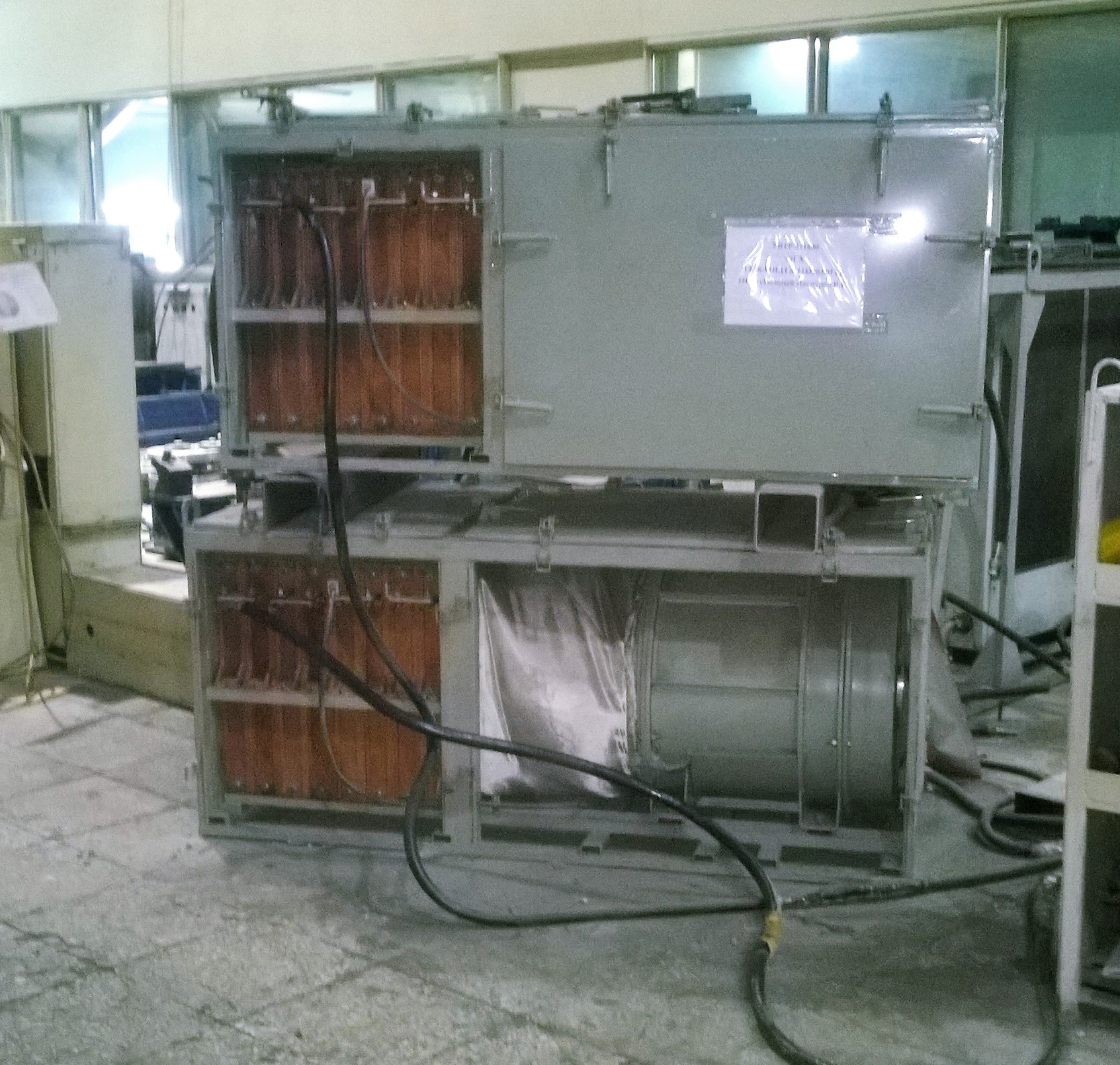
The orange section is the resistors themselves (insulators and stretched between high-temperature tape), and the round barrel is a motor with a fan. So the braking resistor is a big hairdryer. In this case, the fan motor is of direct current, and it is connected in parallel with the brake resistor. It turns out that as the voltage across the resistor increases, the fan speed also increases, which is very convenient. The air flow from such a resistor with its power of 1 MW does not burn at all, but is very pleasant, especially in cold weather :) Only a fan at full capacity is utterly noisy.
Control system
How is all this iron controlled? Each converter has its own controller. The controller in this terminology is such a board, which is based on a microcontroller (processor with memory and peripherals on a chip) and its binding. The binding usually includes a clocking and power supply system, operational amplifiers for the ADC, buffer chips for discrete inputs and outputs, and drivers for communication interfaces. Controllers are usually made more or less universal and are installed, depending on the task, on some basic board, which already contains everything else for the implementation of a specific device.
All controllers are connected via an industrial CAN network. Why can? First, it is the automotive standard; secondly, it is sufficiently fault tolerant and undemanding to cables, and thirdly - there are only three wires.
In our implementation of KTEO 5 controllers are used. Two on traction motors, one on a generator converter, one on a brake resistor converter, and one as a top-level controller in the cab.
Generator and Resistor Controllers
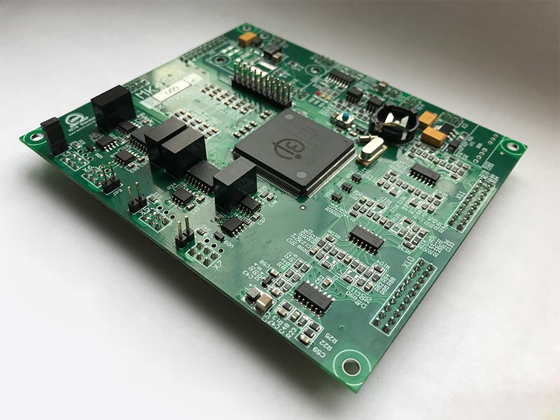
As a generator controller and brake resistor, we use
such a product , a motherboard based on the Texas Instruments TMS320F2810 motor-control microcontroller with a frequency of 150 MHz and 64k of flash memory.
In fact, from the point of view of the key management task of the converter, there is nothing for such a controller to do there — you could do it, sorry for the expression, arduin. However, these controllers still poll a bunch of temperature sensors, implement some logic to control the fans and pumps of the unit, participate in the CAN network exchange, measure the generator rotational speed, etc. Therefore, to speed up development time and to unify with other manufactured equipment, it was customary to use such redundant, but time-tested controllers.
Traction Motor Controller
With controllers for traction motors all the more interesting. Since the dump truck electric motor must produce a large moment at low and zero speeds, this requires designing the motor and converter for a large phase current in the case of using the usual three-phase motor winding. And so do many other manufacturers, receiving the amplitude phase current, measured in kiloamps. This entails the complexity of laying such a cable (with a leg thick), expensive IGBT keys, and a low switching frequency of such keys.
When designing this machine, we went the other way and manufactured a 9-phase engine. Those. there are three independent shifted three-phase windings. This allows you to reduce the current load on each wire and the key, and make the converter a type of small keys of the same type. However, from the point of view of the control system, the task becomes more complicated: you need to manage one controller at the same time with 18 inverter keys! And an additional two key winding. Moreover, since the electric machine is unified, and the three-phase windings are inductively coupled, it is impossible to divide the task into several controllers - synchronization is required between all PWM timers controlling the keys. The figure below shows the structure of the traction motor converter.

Thus, a microcontroller with a minimum of 18 outputs of PWM (excitation winding due to large inductance can be controlled without using PWM, programmatically opening and closing keys in relay mode), a lot of ADC, a rotor position sensor interface (DPR) was needed. And we already
wrote about such a microcontroller. This is a domestic
K1921VK01T microcontroller on the ARM core and a frequency of
100 MHz . He just has 18 PWMs and everything else for controlling engines. Therefore, we used it
in the controller , since there are not so many reasonable alternatives.
By the way, to control the traction motors, the vector control, slightly modified for a multi-phase case, is used, the principles of which are described in detail in
this article , and the free software version used as the basis for development is
here .
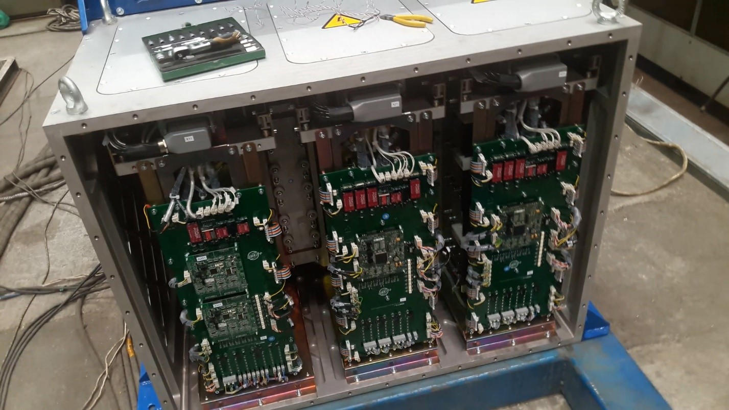
Here is the open control cabinet with installed controllers. Here, to the left is a block of a braking resistor and a generator with two controllers side by side, then blocks of right and left traction motors. The power switches are located in the depth, and the base board with controllers installed in it and some power buses are visible from the outside.
Top level controller
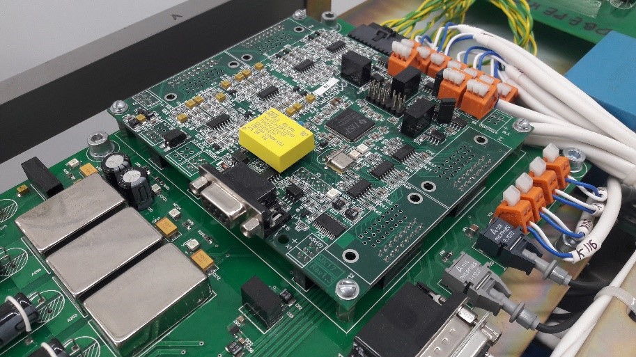
As a top-level controller, a separate controller was developed (for this and other similar projects) based on two Texas Instruments TMS320F28335 microcontrollers. Why two? Firstly, this device has a lot of discrete and analog I / O, many legs are needed, and secondly, for some tasks we needed three CAN interfaces (for different subnets of the car), and the microcontrollers we have mastered only two. However, specifically in the draft dump, the second crystal is not used (not soldered).
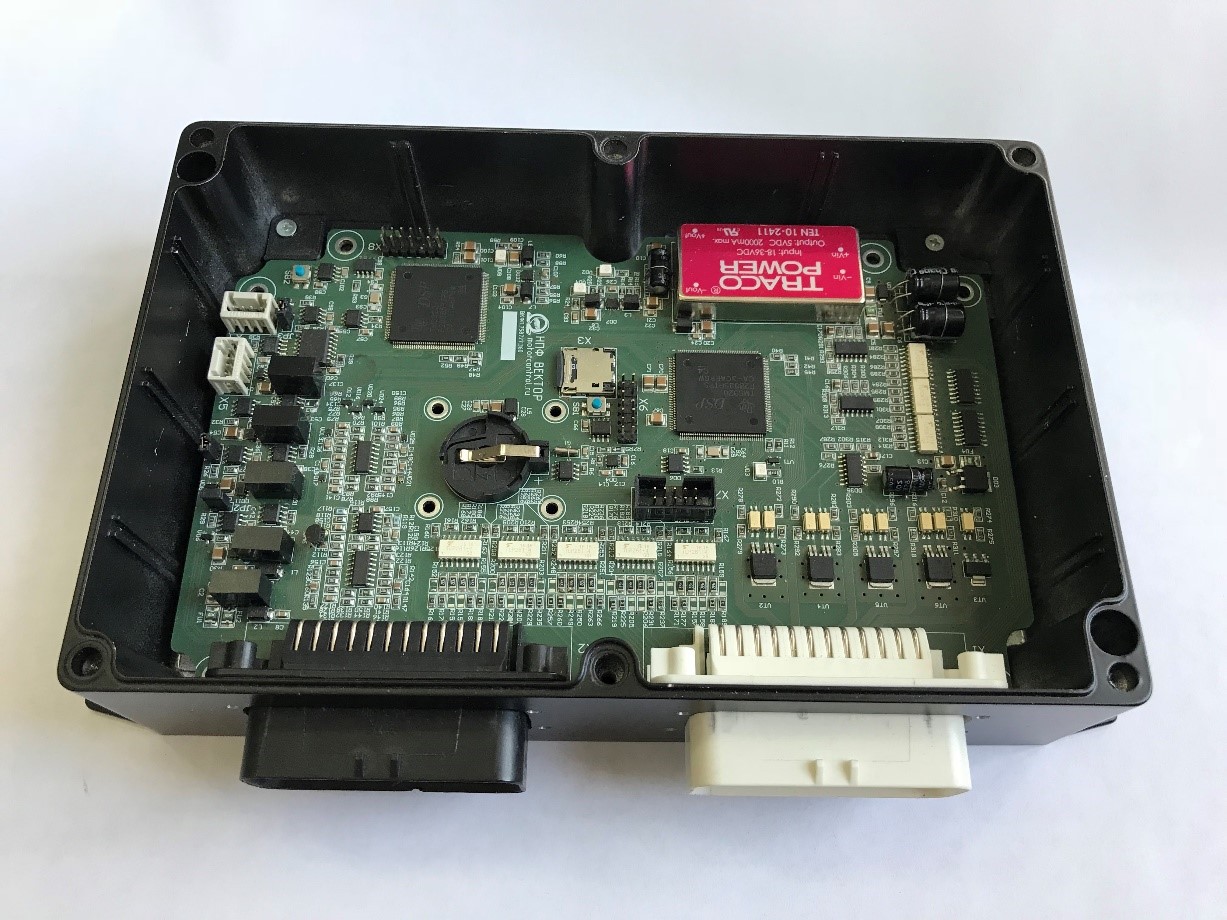
On the board, among other things, you can see a slot for a micro SD card - the KVU saves all the logs (the entire network exchange) in a circle, erasing old ones. Therefore, the HLC also performs the functions of the “black box”.
How difficult and how long to make such KTEO?
From scratch, without experience, of course unreal. We undertook this because we already made similar decisions, we already have experience in designing converters, motors, we have mastered software for controllers, etc. Those. for us, in fact, it was another version of the layout of what we already know how to do. But since the design is somehow new, in the process of testing and commissioning, a myriad of problems still crawled out, which were pulled by all sorts of improvements, both hardware and software. But more about this in the next article.
By the time the development took about two years. From the moment of the beginning of conversations about the project to rolling out the dump truck from the shop under its own power. This is, in fact, a very fast pace. At the same time go, of course, is not enough. The most important thing is how the car will show itself in operation. What will be “children's” diseases, what “adults”, what will be the resource of equipment: only time will tell. Now the car has passed about 20 000 km and continues to be used.
Conclusion
The next article will tell you how the equipment was tested for this truck, there will be a video with buzzing drives, a history of failures and packings.
And as a small advertisement
This project was carried out mostly by graduates of Moscow Power Engineering Institute. If you want to learn more about the electric drive, hybrid transmissions, control systems of electric drives and all auxiliary equipment, to study the microprocessor used in the industry, we inform you that the Department of Automated Electric Drive (AED) of NRU "MEI" spends 13.04.02 " Electric power engineering and electrical engineering ", training program -" Electric drive and automatics ".
Read more - under the spoilerIn the magistracy in this specialty, you can enter on a competitive basis on the budget form of education or on a fee basis without competition. Non-resident provided hostel.
The program of preparation of the department of AEP can be found on the website of
NIU MEI .
More information about the rules of admission, the deadline for submission of documents and admission tests can be found on the
website of the selection committee of NIU MEI.
The Department of Automated Electric Drive NRU "MEI" is the leading department in this specialty in Russia, has more than 20 million rubles. the annual volume of research works, publishes more than 20 articles per year in publications indexed by the Web of Science and Scopus scientometric databases, the department is taught by employees of NPF VECTOR LLC and NPP TsIKL + LLC - one of the leading enterprises in areas of electric drive and hybrid electric transmission development.
Read more here:
www.aep-mpei.ru