In 1974, Texas Instruments released the first 4-bit microcontrollers of the TMS1000 family, and Intel in 1976 began production of the 8-bit microcontrollers of its famous MCS-48 series. And then it began.
Because of the cheapness and self-sufficiency of microcontrollers (then they were called directly - a single-chip microcomputer), consumer electronic devices have become smarter and their number has increased more than ever before. With the advent of microcontrollers, such a class of devices as portable electronic games emerged, the scale of the “disaster” can be estimated at
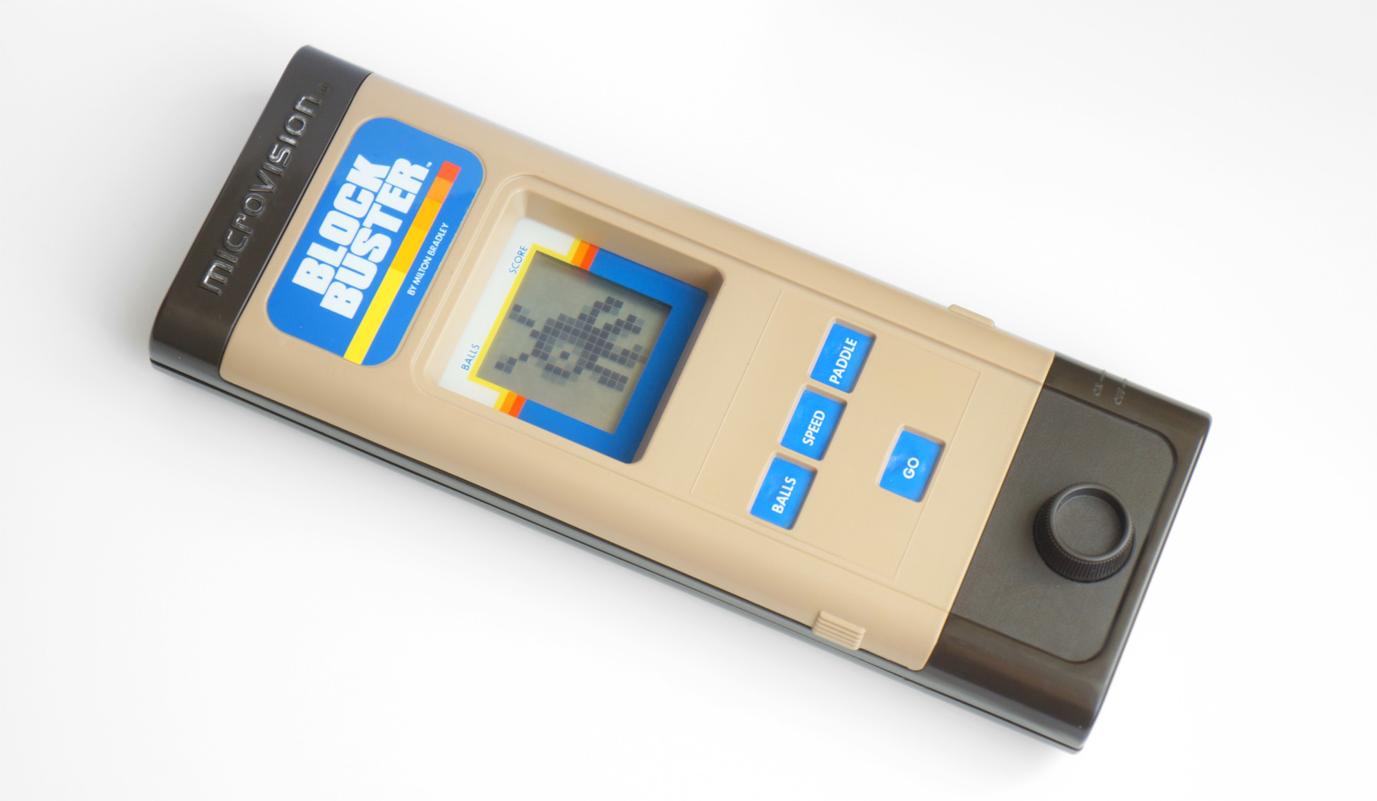
this link . Among all this variety of early games, one stood out, which I will discuss in this post - this is Milton Bradley Microvision, the first portable electronic game with interchangeable cartridges in which both the above-mentioned microcontrollers were used. I will also try to elaborate on the specifics of development for this console.
general description
Microvision was released in the United States nearly forty years ago, in 1979. In total, 12 cartridges with games were sold for it, among which were the bundled Block Buster console (similar to
Breakout ), sports games — Bowling and Baseball, the electronic version of the well-known board game
Connect Four , Pinball, and others. Most of the games can be evaluated on the
MVEM emulator, which was made on the basis of an interesting
series of publications , of which I also learned a lot of useful information. Here I will not dwell on the description of the original games of the console, but immediately move on to its inner world.
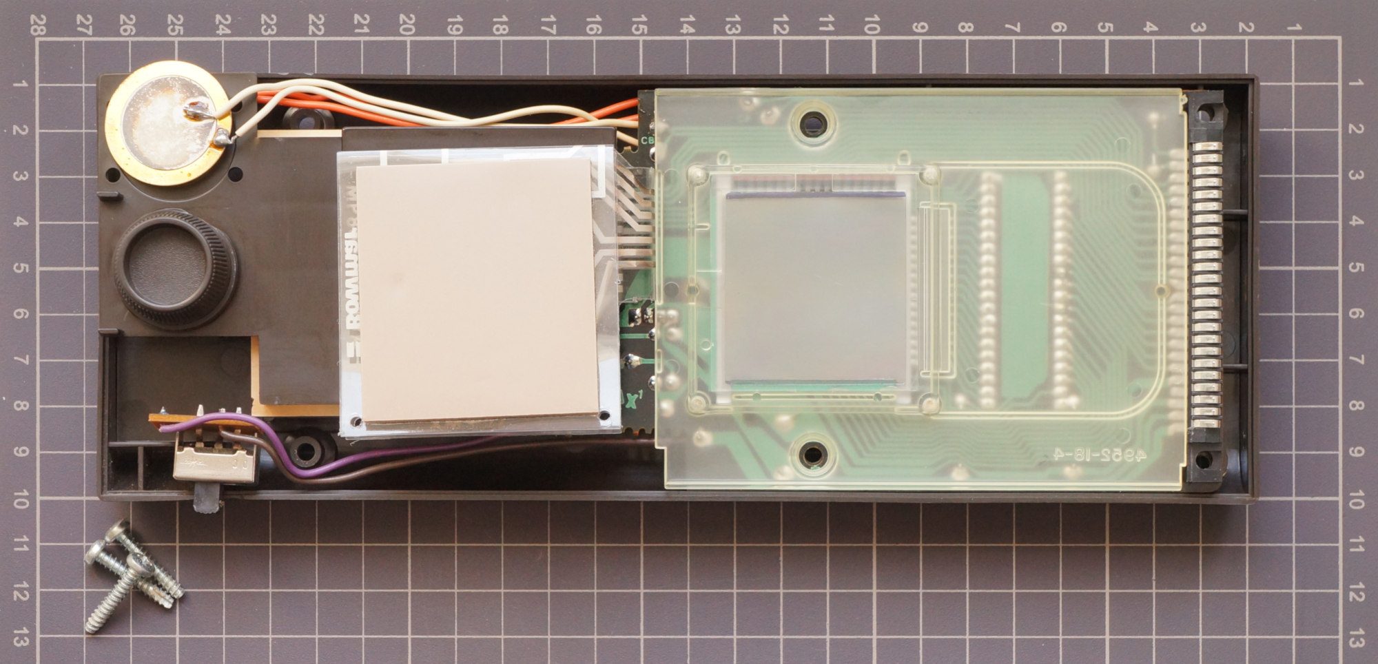
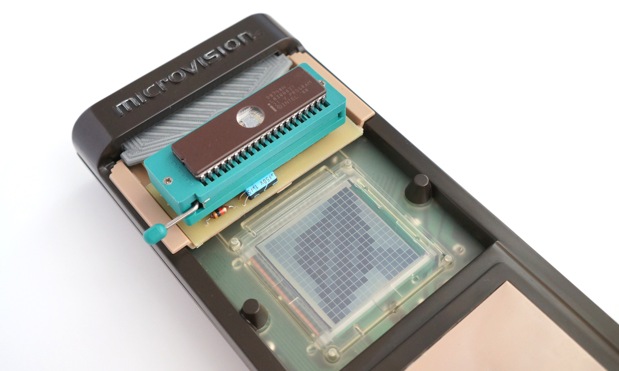
An important feature of the console is a 2-inch liquid crystal display with a resolution of 16x16 pixels. Quite primitive by today's standards, but in comparison with the LED assemblies used in portable games and vacuum-luminescent indicators, the matrix LCD screen was quite a progressive step. In addition to Microvision, in the same year, the Mego Mini-Vid series of electronic games with a similar screen went on sale, though 13x20. Apparently, at that time, these were the only devices widely sold with matrix LCDs of this resolution.
The display is controlled by the Hughes SCUS0488 chip - this is a matrix LCD driver. The driver’s power supply is provided by a UA79MG negative voltage stabilizer with a pair of capacitors and resistors strapped — that’s the whole elemental base.
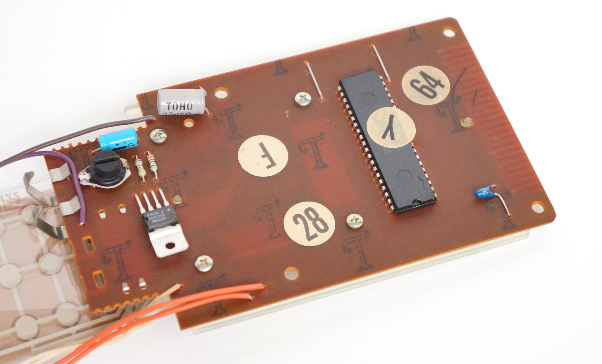
In the case of the console, there are also controls - a 4x3 push-button matrix and a variable resistor of 10 kOhm as a paddle. To play sound there is a piezo dynamics.
The most important thing is why Microvision went down in history, but everyone forgot about the Mini-Vid mentioned above, this is the use of interchangeable cartridges.
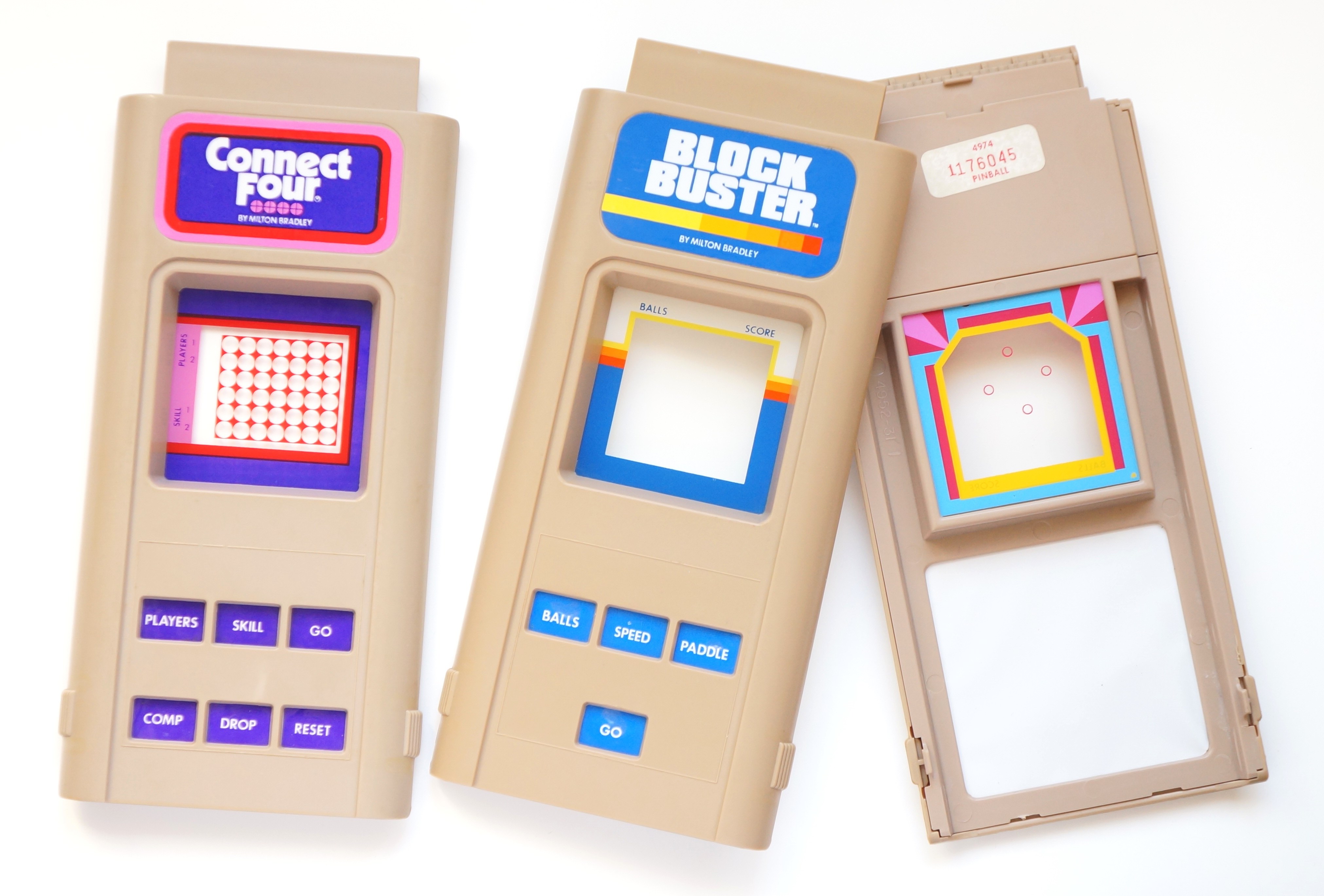
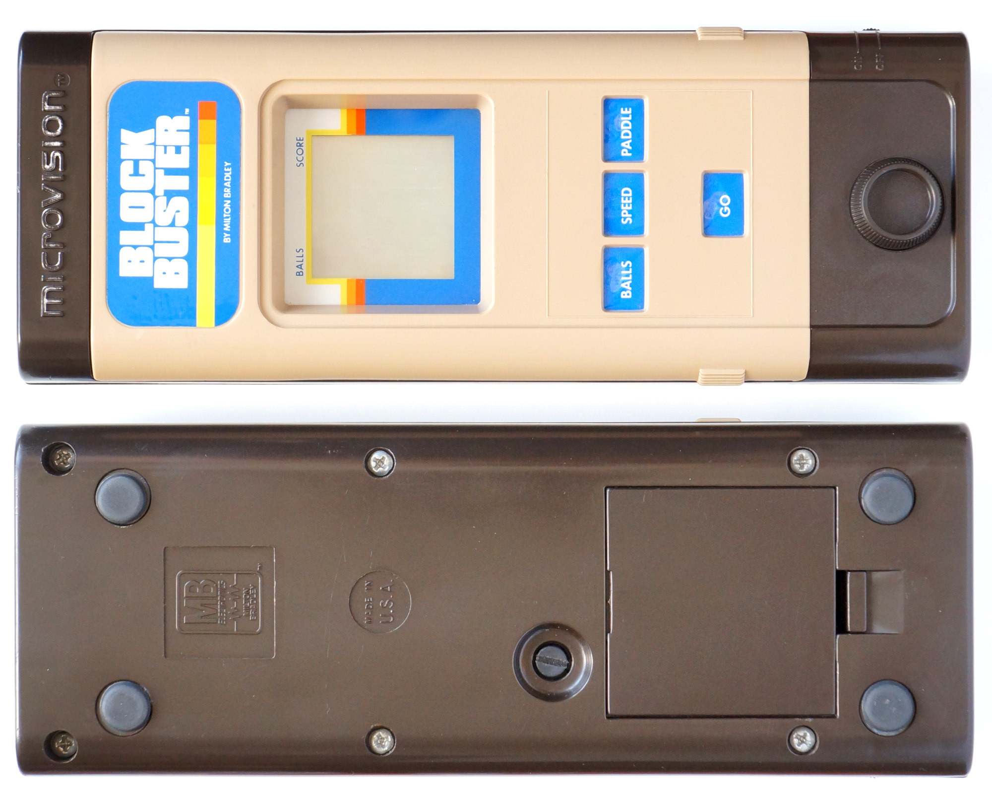
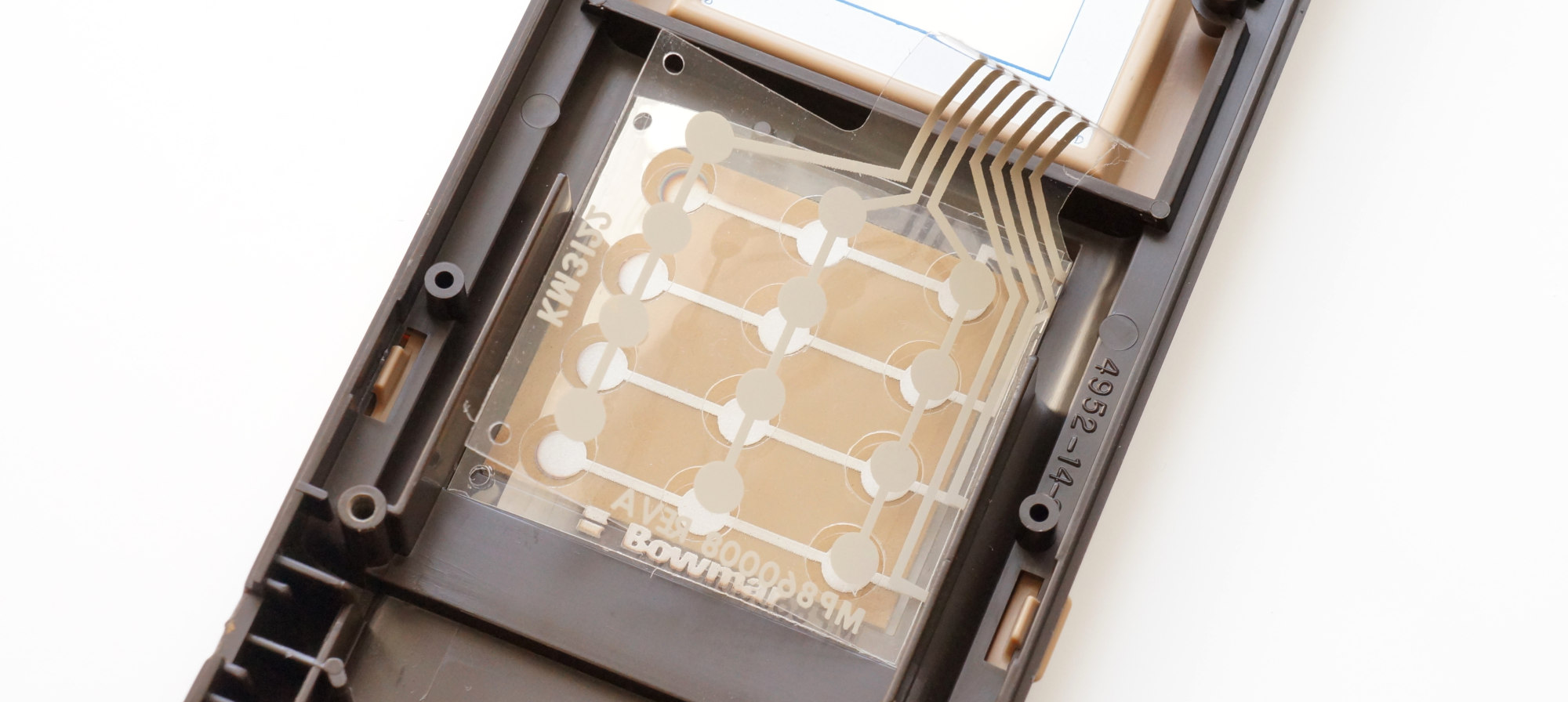
Externally, the cartridge was a detachable upper part of the body. In the center of the cartridge there was a plastic window covering the screen, on which colored game elements and inscriptions were made for each game individually. Below were the holes for the buttons, covered behind with a thin film on which the signatures were made, and for each game holes were made only for the buttons used. Probably, this arrangement of the cartridge, according to the authors, allowed the console to be adapted to the specific game as much as possible.
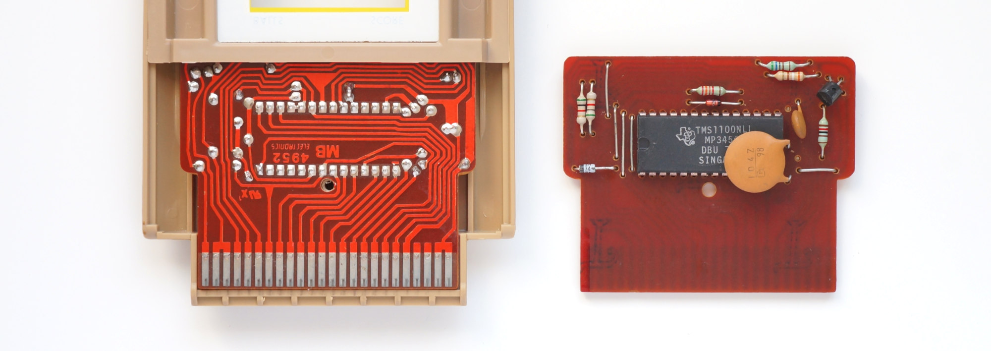 “Block Buster” game board, in the case and on the back side
The electronic part of the cartridge was built on one of two microcontrollers - TMS1100 or Intel 8021 with the necessary strapping. Placing the “brain” of the console in the cartridge may seem like a somewhat strange decision, but it only allowed you to get by with two chips per game. In addition, it also added versatility. At the same time, the price of the cartridge did not seem to increase much due to the presence of a microcontroller (for example, the cost of 8021 in large batches in 1976 was about $ 3).
Nourished all this one or two parallel-connected crowns (8021 was quite voracious). And in later versions, the contacts for the second battery were removed, and the remaining space was recommended to be used for a spare battery. Apparently, this was due to the fact that users often confused polarity, getting a rather dangerous short circuit.
Outset
I bought this ancient console in order to write some game for it and make a cartridge, and having copied the element base of the original as much as possible.
But there is one significant problem - that the TMS1100, that the Intel 8021 had a masked ROM, i.e. programmed at the factory during the manufacturing process. For the microcontroller from Intel, there is a way out: 8021 is a stripped-down version of the 8048, which also had a masked ROM, but Intel produced an analogue of the 8048 with a programmable ROM - 8748, and in the version with ultraviolet erasure as well as cheaper once-programmable ones.
Unfortunately, the situation for the TMS1100 is much worse - there was a debugging version of the chip that works with an external ROM - TMS1098, but it is very difficult to buy it now, if possible. In addition, the microcircuit was made in the DIP-64 package, it is huge in itself and will not fit into the cartridge in length, but a rather large ROM is also needed.
In general, the UV erasable 8748 is what you need, and the final cartridge can be made on a non-erasable version.
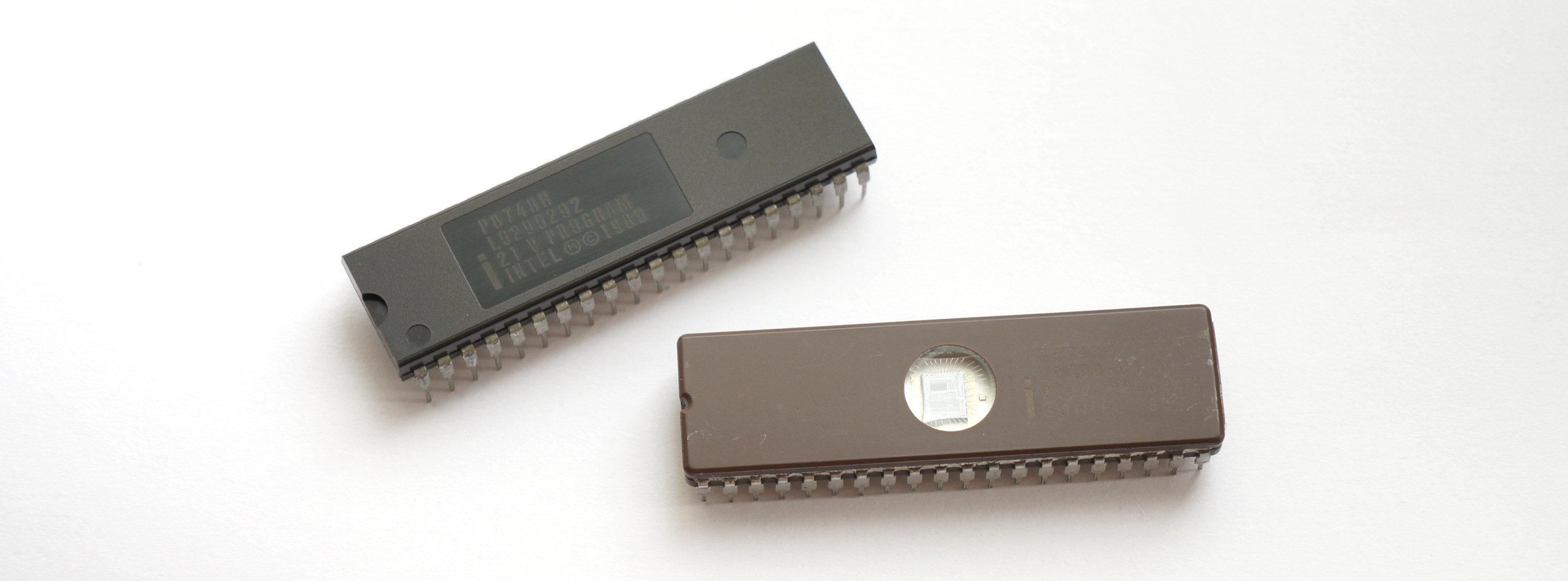 On top, one-time programmable P8748H and on the bottom UV erasable D8748H
Intel 8021
Below is a brief description of exactly 8021, not 8748, because I will use only the trimmed features of the 8021 in order to have only resources initially allocated by the developers of the console.
The memory subsystem, like the entire MCS-48 family, is based on a modified Harvard architecture. Program memory - internal ROM with a capacity of 1024 bytes, data memory - 64 bytes of dynamic RAM.
The organization of RAM is shown in the following figure:

Cells 0-7 occupy directly addressable working registers R0-R7, and R0 and R1 can be used as pointers for indirect access to all RAM cells. Cells 8-23 are used for the 8-level call stack, although they can also be used through R0-R1.
The microcontroller has a built-in clock generator, the reference frequency is set by external quartz, RC-chain or LC-chain. The machine cycle lasts 10 clock cycles, and each clock cycle takes 3 periods of the reference frequency. The maximum frequency is 3.58 MHz, while the machine cycle lasts 8.38 μs. The minimum frequency is limited to the specifics of the DRAM and is 600 kHz.
8021 contains two 8-bit ports and one 4-bit port, which can also be used to connect an I / O port expander, 8243 chips. All ports are quasi-two-directional.
In addition, the microcontroller has a built-in eight-bit timer / counter. In timer mode, the counter T is incremented by 1 every 32 machine cycles. If T overflows, the TF flag is set. In the counter mode, the pulses arriving at the tested input T1 are counted.
The command system contains 64 instructions, of which 36 are executed in one cycle, and 28 in two. Most instructions are single byte.
List of instructions with brief descriptions Training
With the purchase of the 8748, there were no problems; the main thing to note is that the chips were manufactured using different technologies. The earliest NMOPs, which required 25 V for firmware, were marked D8748. By the end of the 70s, these microcontrollers were built using the HMOP-E technology (an improved version of the NMOP from Intel), were labeled D8748H and required 21V already. The same voltage required a later clone from NEC (mPD8748H). The one-time programmable version was labeled P8748H.
The UV eraser was purchased by the simplest and cheapest Chinese with a mechanical timer, which, as practice has shown, copes with its task perfectly (although there is no accuracy of the timer at short intervals). It reliably erases the ROM of the microcircuits in ~ 2.5 minutes. Later, I bought the ZAX Quick-EII eraser for a symbolic price from Japanese hands, I don’t even know what year it is, in appearance the beginning of the 90s. He uses a xenon flash and erases 8748 in 3 (!) Seconds, literally. Video (not mine) with a demonstration of work can be viewed
here .
The main problem was the programmer. Support for this obsolete Intel family of modern programmers is available only at a cost of $ 300 and up. Although there is a relatively cheap amateur Willem, which can work with an MCS-48 through an adapter, it needs a LPT, which did not suit me at all. I had to solder myself. I, let's say, a novice radio amateur, so I was busy with him for about a week, ditching one of the two 8748 arriving at that time (although I am amuse myself with the thought that it was originally such). Based on the scheme published
here , only adapted it for Atmega and more convenient 24V power supply. All this was soldered on a breadboard:

It turned out, of course, rather inconspicuously, and one of the mosfets works at the limit (even a little beyond), but in the end, the programmer coped with his task and served me well.
So, everything is ready, the test firmware flashes the LED fun, it is time to make a cartridge.
Cartridge
The bulk of the cartridges worked on the TMS1100, because Signetics, which produced 8021 under license from Intel, could not provide the required MB of chip supply. Even some games that were already written for 8021 had to be ported to the TMS1100. This, by the way, made it possible to abandon the dangerous bundle of two batteries, since the TI's microcontroller consumption was only 0.1W versus 1W for Intel. I have only one of 6 cartridges with 8021, this is a game of Connect Four, it was taken as a basis.
I tried to make the board as similar to the original as possible, but, of course, I had to make changes. First, the chip size (DIP-40 versus DIP-28) and different pinout. Secondly, we had to change the ratings in the oscillating circuit, which sets the clock frequency, since machine cycle for HMOS versions of microcircuits is 15 cycles, while for MOS versions, which were used in original cartridges, 30 cycles. Therefore, for complete authenticity, my cartridge will operate at 1.25 MHz versus the original 2.5 MHz, while still providing the same performance.
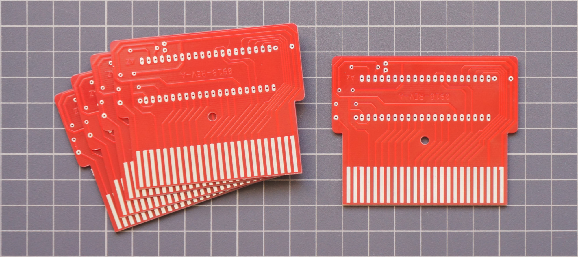
In the photo above, ready-made printed circuit boards ordered in China, and while they were going, I painted and etched the board and assembled such a “debugging complex”:
Finally, the hardware part is ready and you can start programming.
Display
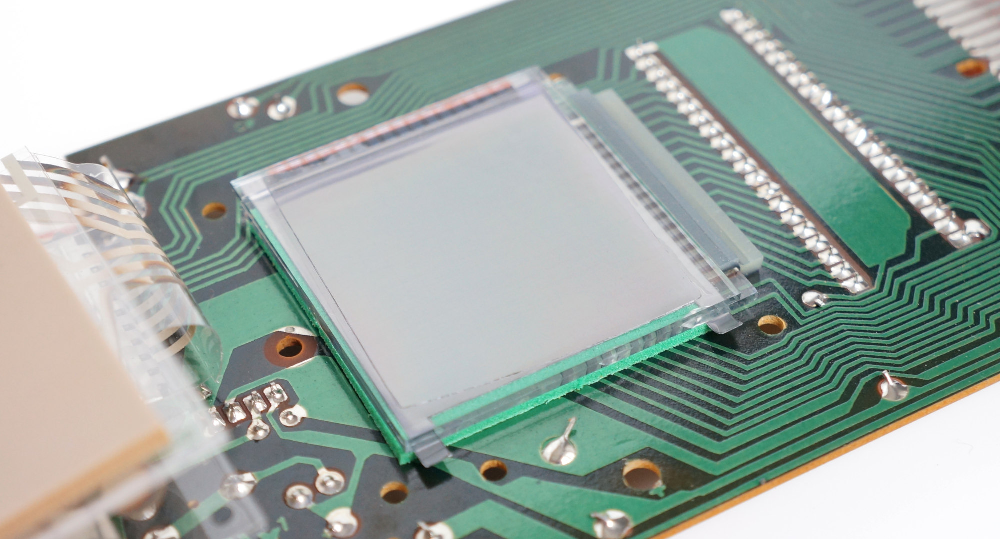
First of all, it was necessary to deal with the conclusion on the LCD display. As I wrote above, it was controlled by the Hughes 0488 driver using multiplexing (an interesting
article was recently published on Habré about this LCD control method). It is the driver, not the controller, so you can't just turn on some pixel and go about your business, you need to constantly update the contents of the screen with a frequency of 30-50 Hz with low-level commands.
The wiring diagram is as follows:

Pinout H0488:
Vdd - power (3-8V)
R1-R16 - Line Outputs
C1-C16 - Column Control Outputs
DATA0-DATA3 - Data Bus
! Data Clk - Input clock data recording
Latch Pulse - Signal latching signal of the terminals R0-R15, C0-C15
The meaning of the chip is as follows:
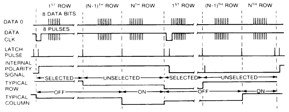
After 4 information lines, the required state of all 32 outputs of the microcircuit is sequentially set (16 for rows and columns). Those. in 4-bit portions we indicate the state of the outputs for rows 1-4, then 5-8, 9-12 and finally for 13-16, and also 4 times 4 bits each, we indicate the state of the columns. Each new piece of data is clocked by a pulse along the line! DATA CLK. After we have sent all 8 batches of data, we set the indicated state of the outputs R1-R16, C1-C16 by the pulse on the Latch Pulse line until the next pulse on this line.
Naturally, in one such cycle we cannot indicate the state of each individual pixel independently of the others; we can only 16 (by the number of intersections of rows with columns). Therefore, to independently update the state of each pixel, you will need to perform 256/16 = 16 cycles.
In addition, it is our responsibility to switch the polarity in order to eliminate the constant voltage of the LCD electrodes, otherwise the display will quickly deteriorate. Polarity switching occurs on the falling edge of the signal at Latch Pulse at a low input level! Data Clock. Polarity is recommended to switch with the refresh rate of the screen.
The above is illustrated by the following datasheet timeline:
All of this, implemented in assembler 8021 (which, by the way, is significantly shortened compared to the assembler of the rest of the family, all for the same authenticity I used only the instructions supported by 8021) might look something like this:
mov R0,
This is my fastest version of the subroutine that displays the image stored in RAM. It runs in 1152 machine cycles (which in our case is ~ 12 μs).
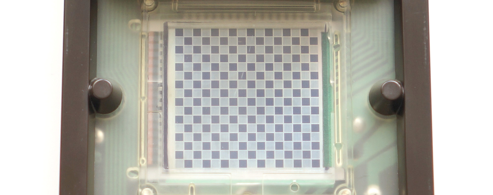
The maximum screen refresh rate is about 70 frames per second (if the microcontroller will not do anything else), which is redundant in principle, therefore, in order to save registers and ROMs, I used other subroutines in practice - slower and more suitable for specific tasks. But, at such a frequency, taking into account the high inertia of this display, it is possible to display images with 4 grayscale gray (like a nyblon on KPDV), quickly changing frames. Or even short four-color animations:
As you can see, the contrast leaves much to be desired, this is especially striking when all the rows and columns are involved, but there is nothing to be done - the costs of multiplex control.
Keyboard
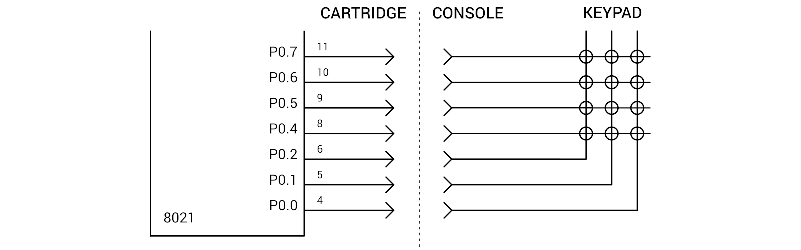
It's all much easier. The buttons are grouped into a matrix of 4 rows and 3 columns. The rows are connected to pins p0.4-p0.7, the columns to p0.0-p0.2.
As I noted above, ports at 8021 are quasi-two-directional, therefore, to find out the status of the findings, you must first send units to them. Those. When data is entered, a conjunction occurs between the input signals and the contents of the buffer that corresponds to the latest data output to the port. A keyboard survey looks like this:
mov a,
Paddle
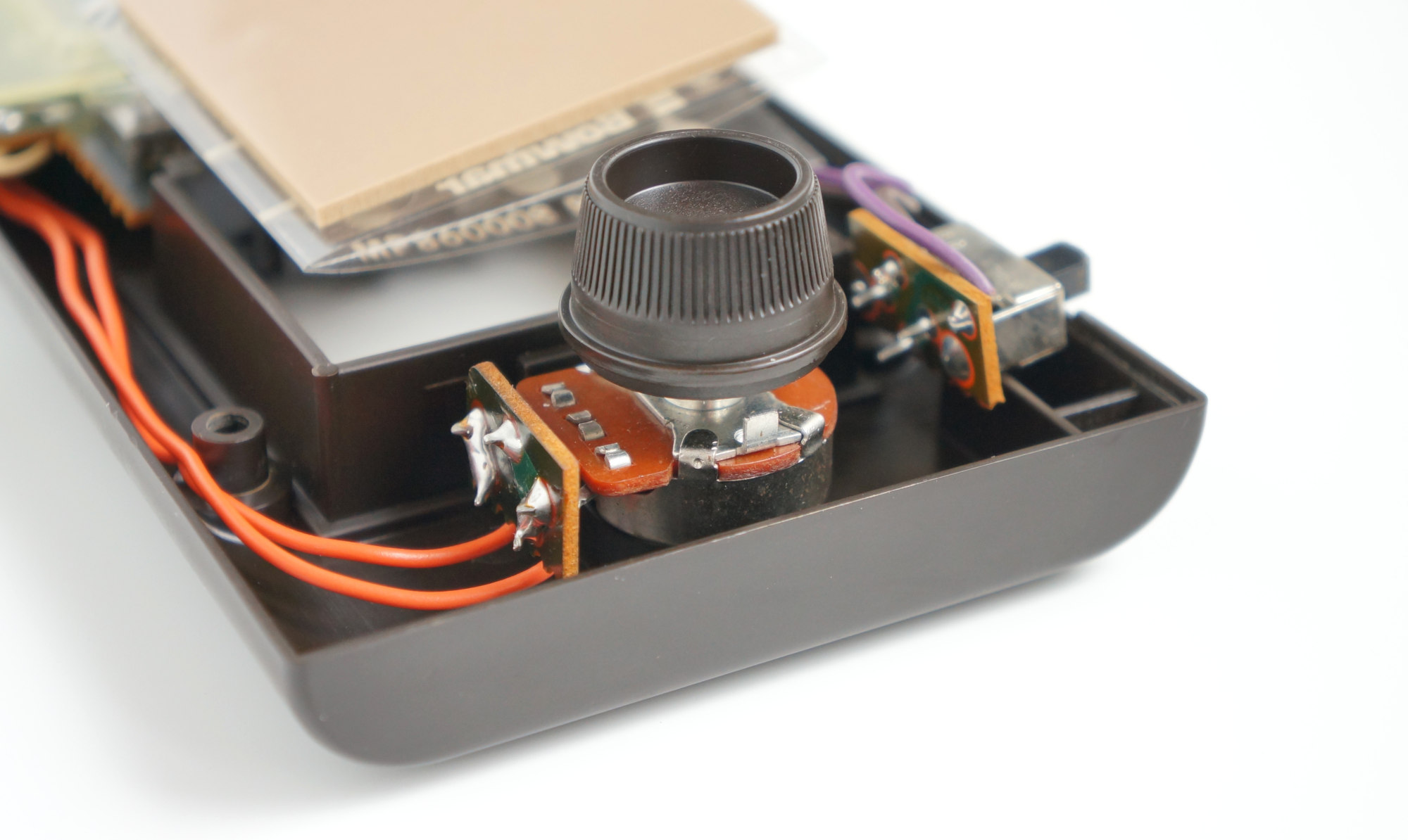
Or, in Russian, the manipulator wheel, mounted in the lower part of the console, is a 10kΩ variable resistor with a decorative handle, rotating which can be controlled by something in the game. Of course, there was no ADC either in the 8021 or in the TMS1100. The rotation angle was determined by the charge rate of the capacitor, which was wisely soldered on the console board.
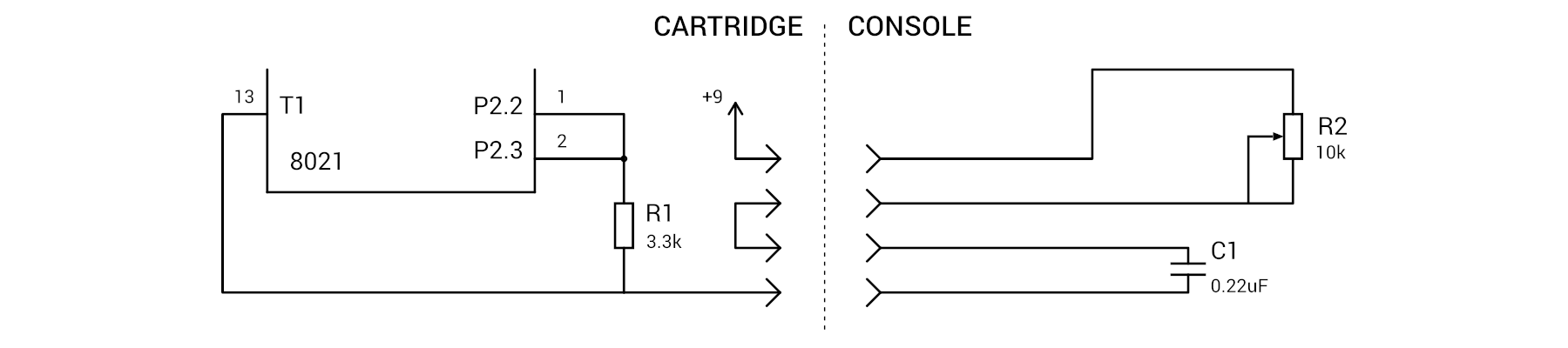
It all works in the following way: as long as the P2.2-P2.3 pins are high, the capacitor is discharged and there is a logical unit at the input T1 being tested. After we install a low level on P2.2-P2.3 pins, the capacitor will start charging and after a while, exponentially depending on the resistance of the variable resistor, the voltage drop across it will become such that T1 is set to 0. It only remains to detect the time before the appearance of zero on T1, which will be proportional to the angle of rotation of the paddle (more and more interesting about such schemes can be found in
DI HALT'a ). In code, it might look like this:
clr a mov r1, a outl p2, a ; 0 P2.2-P2.3 loop: inc r1 ; r1 jt1 loop ; T1 mov a, #00110000b ; 1 P2.2-P2.3 outl p2, a ;
Sound
It is quite simple here, the piezo-dynamics are connected to the two lines of the port P2.0 and P2.1, all we need to do is alternately jerking the legs with the desired frequency.
What happened
In the end, I wrote two games - Tetris and some kind of Flappy Bird. For debugging, I used Intel D8748H and the clone NEC D8749HD that differs only in the size of the ROM. The
8048 Integrated Development Environment was used as an assembler and debugger. In the process I got an unforgettable experience - constant poking microcontrollers from console to eraser, from eraser to programmer, and from there back to the console and all this is accompanied by the hospital smell of ultraviolet-ionized air ...
Finished programs were recorded in single-programmed Intel P8748H which were decoupled by printed circuit boards arriving by then.
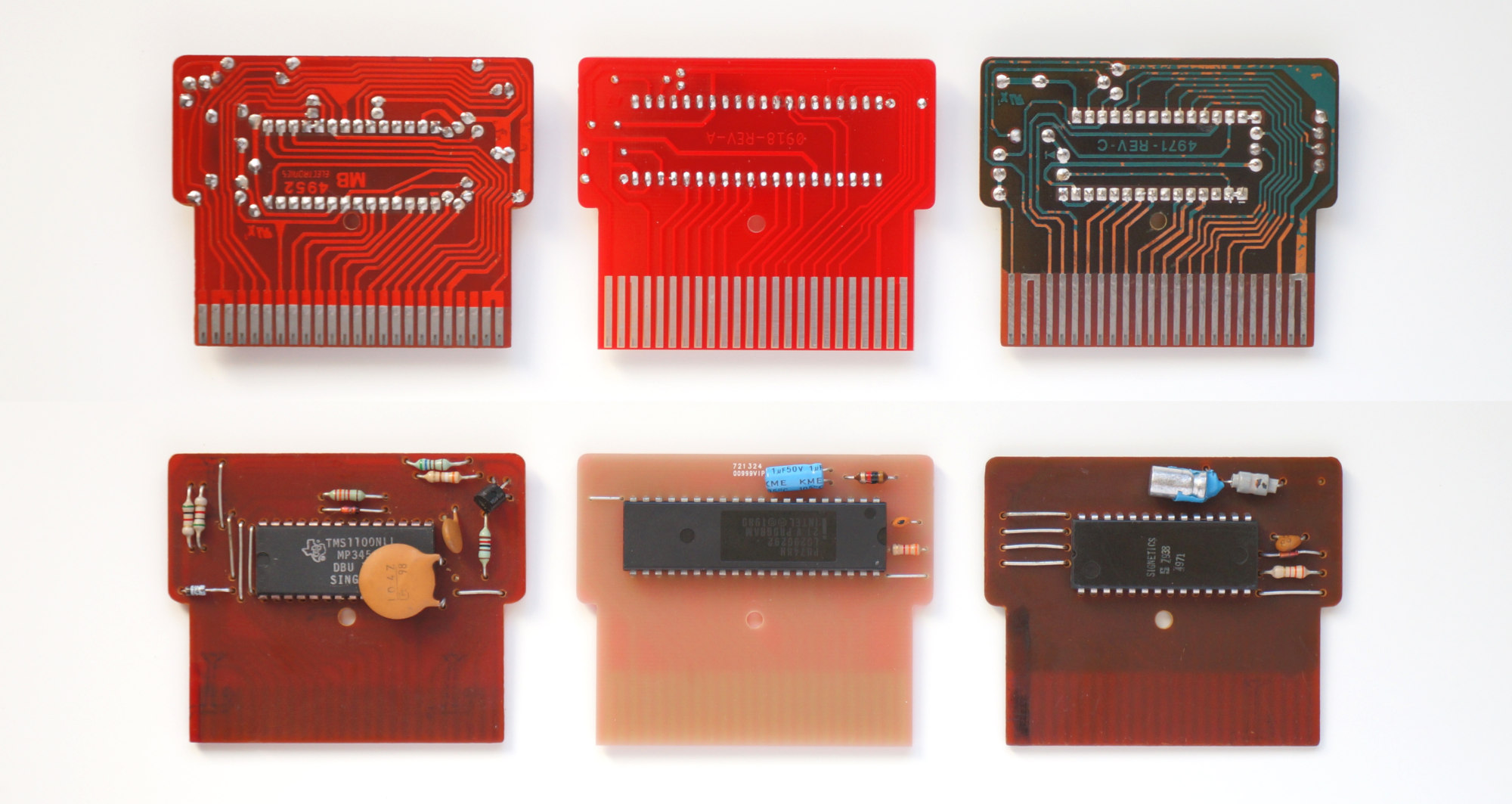 Comparison with original boards, from left to right: Block Buster, My version, Connect Four
I had to use the original one as the case; I just had one of the two available cartridges from the Block Buster game turned out to be inoperative.
The second game did not have enough corps:
Conclusion
MB Microvision was produced until 1981, and although sales at the start were quite successful, a small number of games (13 cartridges were released) and quality problems are usually called the reasons for the decline in sales. I would add to this still an overly large size, especially compared to the Nintendo Game & Watch series that had become a hit then.
Source codes and schemes
published on GitHub