In the Large Hadron Collider (LHC), an underground particle accelerator 27 kilometers in length, crossing the border between Switzerland and France, two particle beams collide with each other, moving at a speed close to the speed of light. The results of high-energy collisions give us information about the fundamental interactions and the simplest constituents of matter. In order to keep the beams on a circular path within the accelerator, a constant magnetic field is required. Superconducting dipole magnets are responsible for this, which with the help of a strong magnetic field deflects the passing bunch of particles at a small angle.
The development and maintenance of the performance of such complex electrical systems is a very important engineering task, which uses modern innovative solutions. In our note, we will describe how, using multiphysical modeling in COMSOL Multiphsycics ® , the European Center for Nuclear Research (CERN) engineers investigated transients in superconducting magnets and BAK magnetic circuits to create a system of protection against failures, which will avoid costly downtime of the collider cooling systems .
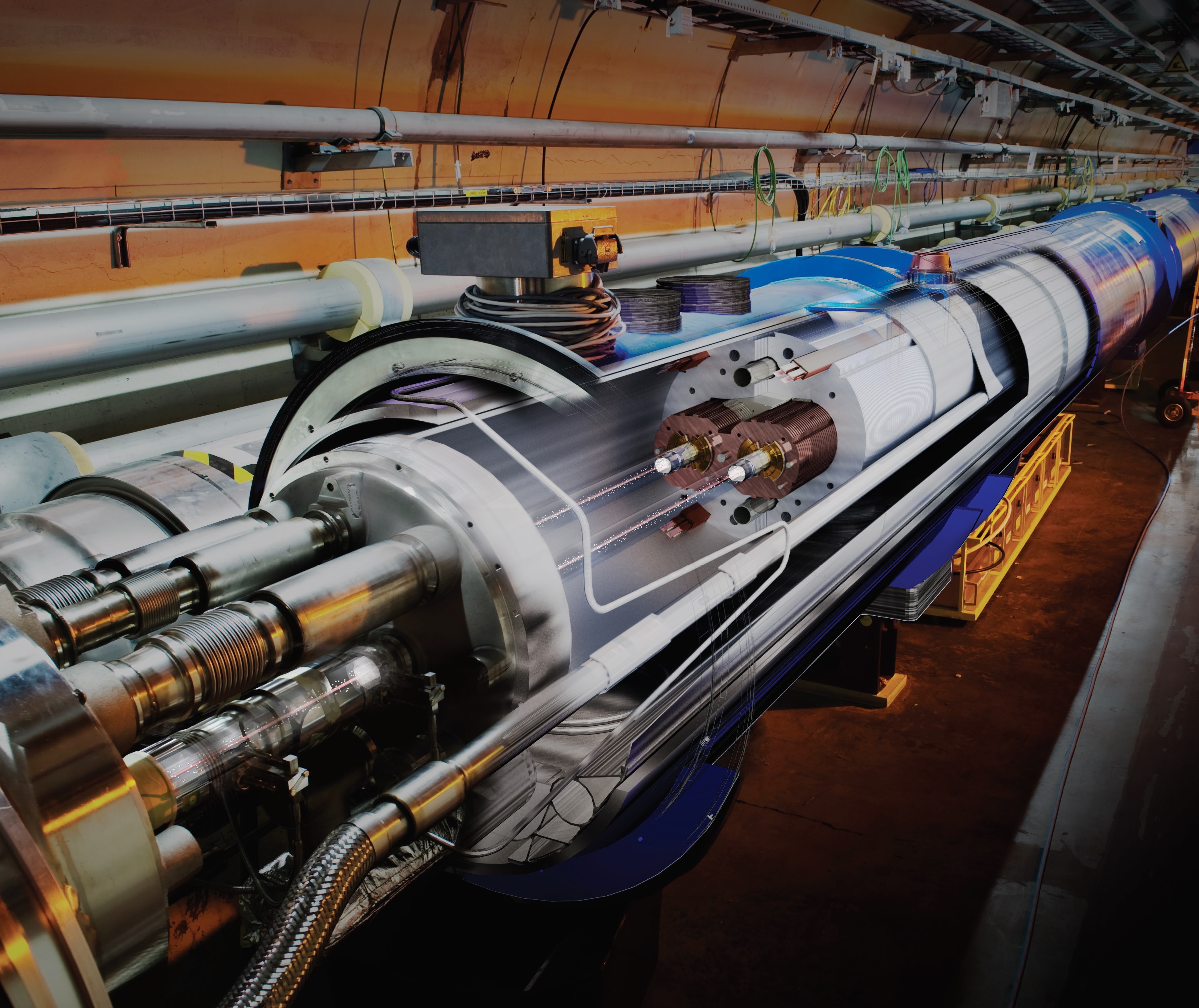
Image courtesy of CERN. © CERN.
The operation of the magnetic system and the detection of superconductivity failure
Powerful dipole magnets that consume up to 12 kA of current and create magnetic fields of up to 8.33 T, support the movement of particles inside the LHC along a circular path. The magnets (Fig. 1) are cooled to a temperature of 1.9 K — lower than in open space — so that the windings of the magnets (Fig. 2) remain in the superconducting state. Theoretically, such modes of operation should ensure constant current circulation in the windings of magnets without resistive losses. In fact, the windings may for some time partially transfer from the superconducting to the normal state.

Fig.1. Detailed view of the aperture of the main dipole magnet. Superconducting windings are held by belts of austenitic steel, which withstand electromagnetic forces of 2 MN / m per quarter of a coil (quadrant) at a nominal magnetic field.

Fig. 2. Left: cross section of the main dipole magnet LHC. Red and blue are superconducting windings that hold particles in a circular path. Gray marked iron yoke. Right: high-current superconducting magnets BAK, including superconducting microfuse cables in a copper frame.
Local temperature rises due to mechanical movement, AC losses, and losses associated with circulating high-energy proton beams can lead to this. Such losses occur around the entire circumference of the installation, when the particles deviate from the ideal trajectory and collide with the surrounding accelerator equipment, for example, with magnets. If the collision energy is high enough, a local jump-like transition of the winding material from the superconducting to the normal state occurs - the breakdown of superconductivity (in English terminology - quench). The superconducting state of a material is characterized by a so-called critical surface, which is determined by the critical temperature, electric current density and magnetic field acting on the superconductor (Fig. 3). The transition beyond the critical surface causes a transition from the superconducting to the resistive state and leads to the disruption of the superconductivity of the magnet.
After the transition to the resistive state during a breakdown, if no protective measures are taken, the winding of the magnet dissipates all the electromagnetic energy stored in its volume. In one dipole magnet, the LHC stores about 7 MJ of energy - enough to melt more than 10 kg of copper. Dispersion in the windings of megawatts of energy can lead to large temperature drops. It should be noted that in all 1232 main dipole magnets of the LHC about 9 GJ of energy are stored - as much as 1.5 tons of dynamite. In the unlikely event of a breakdown of superconductivity with nominal energy and without protection, the powerful accelerator magnets are likely to be irreparably damaged. It will take up to several months to replace a faulty magnet, during which it will be impossible to work with particle beams, i.e. installation will be idle.
Lorenzo Borto, a researcher and electrical engineer at CERN, has developed a two-dimensional finite element electrothermal model of superconducting magnets, which includes research in the time domain and allows you to evaluate how well the newest technological solutions are suitable for automatic systems for responding to a superconductivity breakdown.
During normal operation, the magnets are mostly in a stationary state, and their field (Fig. 3) directs the particles along the LHC ring. The windings of the magnets are superconducting; therefore, the measured voltage drop across the magnets is zero, and there are almost no joule losses. Specialized electronic systems monitor the magnets and quickly respond to a sudden voltage drop across the winding resistance or between adjacent magnets. As soon as the signal exceeds the threshold voltage for the minimum test time, the superconductivity breakdown detection system activates protective measures.
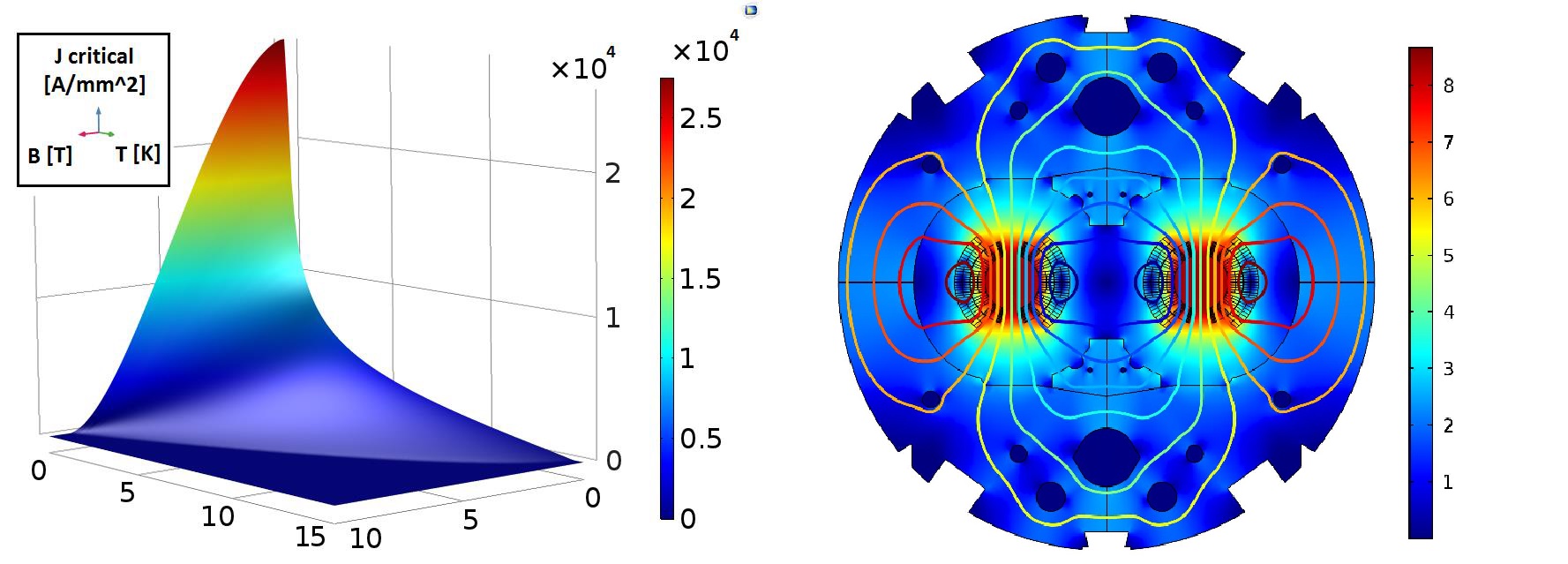
Fig. 3. Left: Critical surface for niobium-titanium alloy - superconducting material of magnets. Right: Magnetic fields in the system at rated applied current.
in superconducting state.
The protection system must be properly designed and adjusted for the magnet it controls, and the electronic part of the system must be properly configured and optimized. On the one hand, the detection system must be sensitive enough not to miss the superconductivity breakdown. On the other hand, too strict response criteria can lead to false alarms. This will suspend work at the LHC and for several hours will disable the installation, reducing its technical readiness.
Superconductivity Breakdown Protection
The system of protection of magnets from the breakdown of superconductivity uses a simple but effective strategy - the spread of the region of failure to the entire magnet, increasing the volume in which energy is dissipated, and not allowing part of the magnet to absorb all stored energy.
“We heat the magnet itself to increase the size of the normally conductive area and dissipate the energy stored in the magnet throughout the entire volume of the winding,” explains L. Borto. This is a paradoxical move: if the magnet works normally, we cool it as far as we can and keep it in a superconducting state, but at the first failure we need to heat the entire magnet as quickly as possible. And here temperature uniformity is very important. ”
A new, but very promising technology for superconductivity breakdown, recently developed at CERN, has been called the “superconductivity breakdown system due to induction loss” (Coupling-Loss Induced Quench system, CLIQ) . Its main component is a charged battery of capacitors connected in parallel to the winding of the magnet. When triggered, the system causes the resonance of the LC circuit, creating an oscillating magnetic field inside the magnet.
The field, in turn, creates induction and eddy currents in the cables, including at the level of individual cable cores. The windings of the magnet are uniformly heated from the inside in a process similar to microwave heating. The CLIQ system has two goals: to increase the volume in which eddy currents occur, and to reduce the time during which these losses translate the superconducting cable into a resistive state above the critical temperature. Energy dissipation in the resistive state is determined by Joule heating, which occurs along the entire length of the winding, and not in one region, while the region of superconductivity failure and the Joule heating region propagate as evenly as possible.
Computational Difficulties and Challenges
A group of electrical engineers at CERN is also implementing a modular approach to modeling transient effects in accelerator magnet circuits based on a set of commercial CAD systems. Lorenzo Borto, specializing in the use of COMSOL Multiphsycics ® software and the Java ® programming language, has developed a unique numerical model that describes the electrodynamics and thermodynamics of the propagation of superconductivity failure. To take into account all possible computational difficulties in modeling these resource-intensive processes, careful preparation and a set of flexible tools were required.
The LHC dipole magnet cross section consists of several hundreds of subregions, each of which corresponds to a half-wound twisted winding cable (on the left in Fig. 4). The breakdown of superconductivity in half-turns occurs non-simultaneously. Due to the local nature of the breakdown, its zone spreads across the cross section, demonstrating behavior that is difficult to model.
“It is important to correctly consider and reconcile the mutual influence of thermodynamics and electrodynamics,” explains Borto. “To numerically describe such a geometry in which a breakdown in each half-turn can occur independently, a separate set of equations is required for each subdomain.”
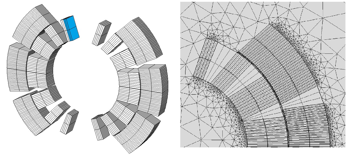
Fig. 4. Left: the geometry of the sections of the magnet. Right: mesh of the finite element model of the magnet sections.
To describe the electrodynamics and thermodynamics of the breakdown process, it is required to simulate the behavior of the system on a scale of the order of meters (cross section of the magnet) and of the order of micrometers (due to the small diameter of the cable cores). In addition, the disruption process develops in a few microseconds and extends in a few milliseconds, and the complete loss of energy by the magnet can take up to one second. Thus, researchers had to simultaneously study three different time scales.
“This is a multiphysical multilevel and multiscale problem, in which phenomena dependent on each other develop on different spatial and temporal scales,” explains Borto.
Most modeling software would not create an efficient computational model, since it would require a grid covering six orders of magnitude and a solver pitch defined by the smallest time scale, resulting in huge amounts of data and excessive time.
To circumvent this difficulty, a group of scientists at CERN used an expression for equivalent magnetization to study the system using the functionality of the COMSOL software (Fig. 5). Instead of calculating on the micrometer scale the paths of induction currents arising in superconducting cables, the engineers simulated these parasitic currents through their equivalent contribution to the resultant magnetic field.
“We used a formulation based on equivalent magnetization proportional to the derivative of the field after some time constant,” says Borto. - This is a combination of the laws of Faraday-Neumann-Lenz and Ampere-Maxwell. This is possible with knowledge of the path of induction currents in the cable, which allows you to set the equivalent time constant. "

Fig. 5. Equivalent magnetization created by eddy currents (A / m) with linear growth at a speed of 100 A / s and a value of 8 kA.
For these transformations, L. Borto used the flexibility of editing standard Maxwell equations and replacing variables in COMSOL. By changing the equations that are solved in software, he was able to adjust the standard formulation based on the vector magnetic potential for his tasks. In addition, an extremely important step was to obtain convenient access to the previous time step of the solution for calculating the derived field.
“Since we already consider induction currents in equivalent magnetization, we do not need additional circulating currents,” Borto said. - I turned off the induction currents in the area of the winding, and this greatly simplified the work. I would say it became the cornerstone of the architecture of our solution. ”
Simulation based on user equations in COMSOLA short video review (in Russian) , which demonstrates how to use algorithms and unique modeling tools COMSOL Multiphysics ® to solve arbitrary systems of algebraic and differential equations, as well as to modify existing physical interfaces.
Without simulating the induction currents in an explicit form, the scientists were also able to significantly simplify the grid (on the right in Fig. 4).
It was difficult not only to model the physics of the system consistently and effectively, but also to recreate in practice a realistic model of the device. At ultralow temperatures, the highly nonlinear properties of materials are described by complex numerical structures that are effectively implemented and controlled by external functions in the C language, organized into a common shared library. In addition, each half-winding winding is described by its own set of variables and operators and has its own micrometer thickness insulation layer. In the exact model of propagation of superconductivity breakdown, it is important to take into account this layer, which can be modeled due to the built-in boundary condition for a thin layer in the package, which does not require explicit grid generation.
The assembly of these repetitive sub-blocks was automated to save time and avoid the influence of the human factor and the corresponding errors. That is why a finite element (FEM) magnet cross section model is created and assembled by a separate Java ® algorithm that turns user input into a distributed model using the COMSOL application programming interface (API) . Such a technique provides sufficient flexibility of the used finite element method for its adaptation to various types of magnets.
Modeling induction currents through an equivalent magnetization allowed scientists to immediately calculate the losses and express them as a function of magnetic field oscillations. The group came to the conclusion that the oscillations of the magnetic field are directly dissipated as losses to induction currents.
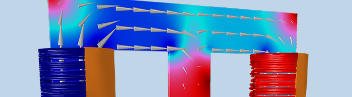
One of the main achievements was the modeling of the superconductivity breakdown process in the main dipole magnet of the LHC after the sudden activation of the CLIQ protection system to prevent the effects of the breakdown. The model, which takes into account the nonlinear properties of materials depending on temperature and magnetic field, demonstrates magnetic field oscillations and eddy current and induction current losses (from the left in Fig. 6) in a superconductor, propagation of superconductivity failure and resistive heating caused by it (centered in Fig.). 6), as well as the final temperature distribution due to the accumulation of heat losses in the winding (on the right in Fig. 6).

Fig. 6. Left: Loss (in W / m 3 ) in eddy current marks generated by the CLIQ system. In the center: ohmic losses (in W / m 3 ) due to the propagation of superconductivity breakdown. Right: Temperature distribution (in K) in the windings after the breakdown of superconductivity with a duration of 500 ms.
The design of the CLIQ system was also verified independently by solving the heat balance equation, and it was confirmed that the magnet reaches the temperature required for propagation of the failure across its volume, and the winding receives the required amount of energy. In addition, the model allowed us to establish lumped parameters related to stalling: winding resistance and voltage drop over time (Fig. 7), which can be used as input data when modeling external electric circuits of a magnet.

Fig. 7. Results obtained in COMSOL in simulating superconductivity failure. Above: the growth of ohmic resistance in the winding. Bottom: voltage measured at the winding leads.
From LHC to future accelerators
The Borto model makes it possible to reproduce interconnected physical phenomena arising from the rapid dissipation of energy and to study in depth the phenomenon of superconductivity breakdown in magnets.
These models are now being adapted for the designed and constructed magnets intended for the modernization of the LHC in order to increase the luminosity (High Luminosity) , as well as for the future next-generation ring collider (Future Circular Collider). The possibility of extending models to three-dimensional problems will also be investigated (Fig. 8). Simulations that go along with the design process help and support the development of new systems for the detection of superconductivity failure. The work of a group of scientists will help protect current and future accelerators from the effects of a breakdown and allow researchers to continue to study the nature of matter without fear of damaging superconducting magnets.
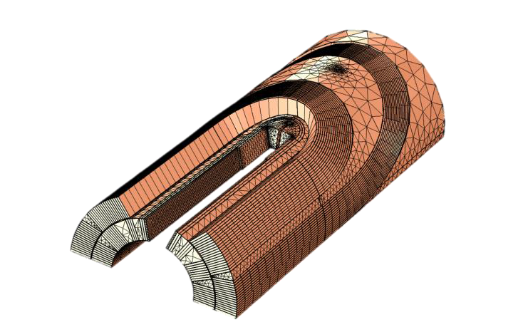
Fig. 8. The proposed geometry and mesh for a future three-dimensional model.
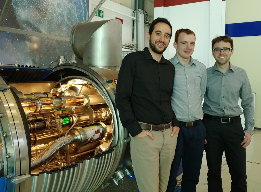
Fig. 9. From left to right: Lorenzo Bortot, Michal Maciejewski and Marco Prioli.
PS Additional Information
The article is based on the IEEE Spectrum magazine . Multiphysics Simulation Insert 2017 (in Russian) .
Main topics of the issue- Piezoelectric fans (Nokia Bell Labs)
- BAC protective systems (CERN)
- Design of electric motors (Faraday Future)
- Equipment components for 5G networks (Signal Microsystems)
- Fuel cells with ion exchange membrane (National Chemical Laboratory of India)
- Production of memory chips (Besi Switzerland AG)
- Modeling and Education Applications (University of Hartford)
- Applications for modeling and additive technologies (MTS)
- Fiber optic pressure sensors (University of Campinas (Unicamp) and the Institute
Advanced Studies (IEAv)) - Lithium Ion Battery Simulation (COMSOL)
Presentation of the results of this work (L. Bortot, M. Maciejewski, M. Prioli, AM Fernandez Navarro, S. Schöps, I. Cortes Garcia, B. Auchmann, AP Verweij. Simulation of Electro-Thermal Transients in Superconducting Accelerator Magnets with COMSOL Multiphsycics ® ) was held at the COMSOL Conference 2016 user conference (Germany): a detailed description and presentation (in English).
For a more detailed acquaintance with the possibilities of our package, we invite you to participate in our new webinar "Basics of Electrical Calculations in COMSOL Multiphsycics ® " , which will be held on July 25, 2018.
More about the webinarFree registration: http://comsol.ru/c/79vj
The AC / DC module contains a whole set of physical interfaces for analyzing phenomena related to various areas of electrical engineering: electrostatics, electrical currents and fields, magnetostatics, and alternating electromagnetic fields, taking into account induction effects. In this webinar, we will systematize all the extensive information about these capabilities of the COMSOL Multiphysics ® package and describe the available tools, settings and features that allow you to:
- Calculate electrostatic and resistive devices and related effects
- Simulate inductors, transformers, electrical machines, permanent magnets and other magnetic equipment
- Investigate related interdisciplinary effects: heating and cooling of electrical engineering (including Joule and induction heating), electrical breakdowns in electrical engineering, plasma effects, tracing of charged particles , electromechanical and MEMS systems.
As an example, we will demonstrate the assembly of a transformer model in dynamics, taking into account a nonlinear core and load. The webinar will end with a question and answer session.