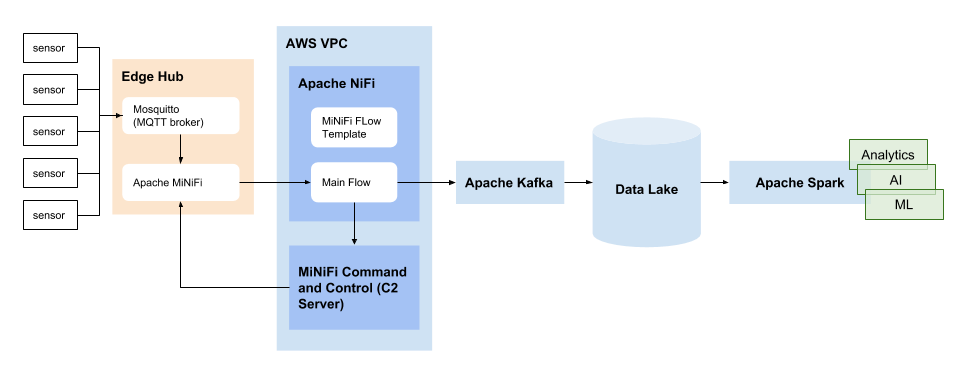
In the previous article, we briefly reviewed the organization and processing of IoT data using the Apache NiFi project. With this article we will open a series in which we will describe in detail about each stage, starting from the devices themselves and ending with DataLake platform analytics, machine learning, prediction of anomalies, etc.

Now let's start with the very first level, the “things” itself, the letter T from the abbreviation IoT. From the device itself, the organization of the communication channel and the use of the MQTT protocol. IoT trend for several years, but for the most part, the idea of it as a light bulb and a socket that is switched on from the phone. But in production, mining, and in various other industries for decades, a variety of sensors have been used, the values from which are collected in production SCADA . Just connect the data stream to the Internet, and we get the same IoT, more precisely IIoT - the industrial Internet of things.
Why is all this necessary if all these decades of SCADA successfully manage the production cycle?
There are several reasons:
- The possibilities of using sensors are expanding, for example, logistics, where a location sensor is installed on a specific truck or car, as well as various additional ones, such as fuel consumption or idle time (waiting at the station until the car is attached) is all beyond the local production network
- The number of sensors on devices is growing, they require more sophisticated processing, which is not always possible to make enterprise capacities
- The capabilities of machine learning and artificial intelligence that have developed due to the growth of computing power, which can be used to optimize production, search for bottlenecks, identify anomalies
As a result, sensors in production are no longer simply sending values to SCADA. We need a software architecture that will allow us to build a chain from the end sensor on a machine to a computing cloud, in which, based on the machine’s history, using a trained model, the message “37% probability of failure of the mechanism” will be sent by an engineer ".
And now back to things! Usually for demonstration of such systems open sets of historical indicators of sensors of any industry are used. But unfortunately in this version, the "touch" system does not work. No, we won't get to the plant, but we will do our simple “thing with the Internet”.
Our field of activity is connected with server infrastructures, but we still have some hobby-electronic skills, so the “thing” will be self-made.
We will choose the simplest monitoring option - a climate sensor; we will collect data on temperature, humidity and pressure.
Component base
For the sensor, take the BMP280 .
Very sophisticated thing, it is intended not only for weather data, but also, thanks to a sensitive barometer, for GPS assistance, for navigation in the building (to determine the floor), for games to help the accelerometer. We will only use it for weather data.
Take as a module the following:

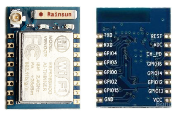
As a controller and a communication channel at the same time, we’ll take, probably a cult one, esp8266 ( https://en.wikipedia.org/wiki/ESP8266 )
In our case, the ESP-07 module:
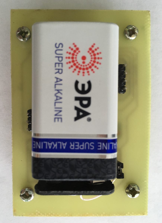
As the power - 9V battery "Krona". Since all devices operate from 3.3V, a downconverter is needed. Hand stretches to put everyone's favorite linear LD1117 :

But everything that lowers the linear transducer - it simply dissipates into heat. The peak current of esp8622 is about 0.4A, which means with a linear transducer (9-3.3) * 0.4 = 2.28W to nowhere. More and melted.
Therefore, we assembled a pulse down converter on the LM2576 :
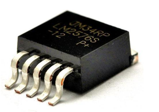
3 amps exactly enough for everyone (for real, that of the component base was, then soldered).
Scheme
Eagle was used as CAD, the scheme was as follows:
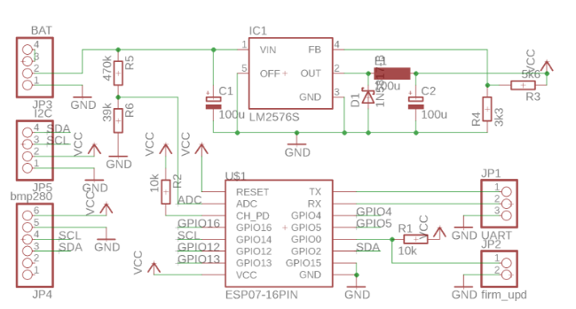
To run esp8622, you need to pull RESET and CH_PD to a plus (turns on the module), GPIO15 to a minus. When GPIO0 is pulled to the ground, the module goes into programming mode, so there is a jumper there.
GPIO02 and GPIO15 are used as SDA / SDL I2C bus lines to connect the BMP280, as well as any other devices to the bus (JP5 pin connector), for example, a display, for debugging right on the spot.
JP1 is used to connect via UART (via a UART-USB converter) to a computer for programming and debugging a module.
Resistors R6 and R5 assembled a voltage divider for the ADC, so that you can monitor the battery charge.
Pay
The layout turned out this:
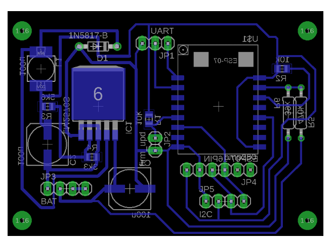
Most likely, in the best traditions of hobby circuit design, violates all possible rules, but most importantly - it works :)
The device itself turned out like this:
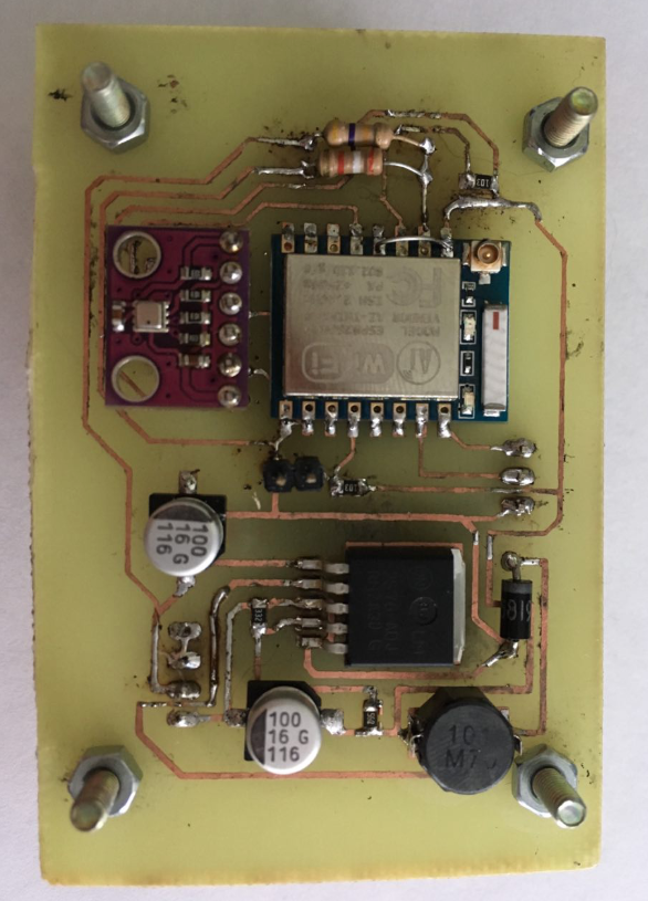
The board is made using laser-iron technology (one of thousands of examples: http://cxem.net/master/45.php ).
Device programming
For a quick start for esp8622, we took NodeMCU firmware.
NodeMCU is a Lua interpreter for esp8622 and a bunch of libraries for various devices, sensors, displays, etc.
To flash a device, you first need to get this firmware. The documentation offers several options, but the simplest of them is the nodemcu-build.com service, which allows you to simply get the firmware by mail by simply selecting the modules you need.
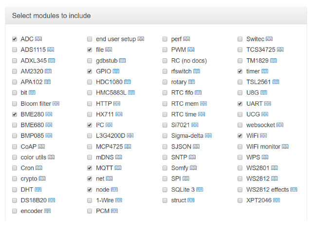
For our device, it is necessary to choose MQTT, I2C (because the sensor is located on this bus), well, the BME280 sensor itself (we have the BMP280, but the library is universal), and also the ADC to monitor the battery. After the firmware is assembled, the service will send it to the specified mail.
Next you need to close the GPIO0 to the ground and put the module into programming mode (jumper JP2), connect the USB-UART adapter and distort the power.
Firmware download is done using NodeMCU PyFlasher . You need to select the appropriate serial port, the firmware itself and for the ESP-07 module - Quad i / O, the other modes will not work.

Have a little patience until the firmware is complete, then remove jumper JP2, distort the power and as a result, our device is ready for user code.
Code
UART settings for connection - 115200 8N1, by connecting to a terminal for a serial port (for example, terminalbpp ), you can directly enter lua commands, a sort of REPL.
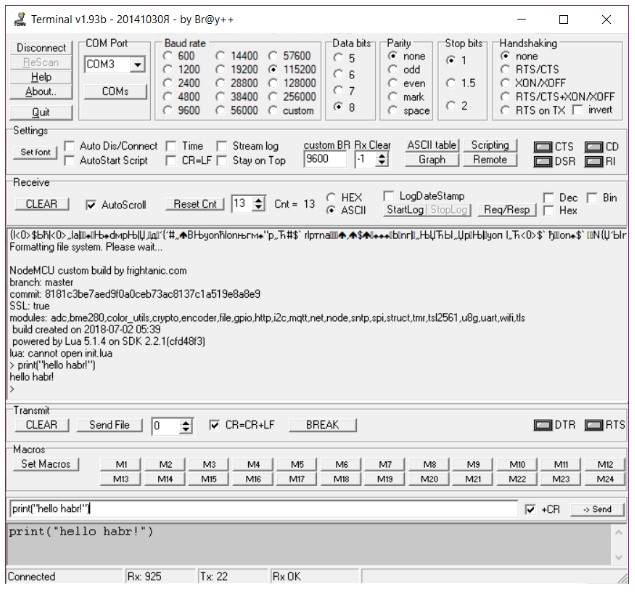
But we are still interested in less ephemeral firmware, so that after a reboot it remains :)
When launching NodeMCU starts to execute the init.lua file (if any) from the flash card. Here we write it.
For a sample we take an example from the documentation:
To load, we used a simple Asmodat ESP LUA Loader utility . It simply pushes into the terminal file.open and Lua writes it line by line with commands.
The logic is as follows:
- We initialize devices
- Connect to WiFi
- Read the sensors
- Connect to the MQTT broker and send readings to the appropriate topics.
- Turn off WiFi, fall asleep until the next measurement
We laid out the Lua script, layout and layout of the board , in principle everything is quite transparent there.
Places that I would like to mention:
The ADC esp8266 input requires a voltage in the range from 0 to 1V and gives the corresponding number from 0 to 1024 at the output. For resistors 39kOhm and 470kOhm - the conversion factor turns out to be about 13. That is, in order to estimate (not very accurately measure) the voltage on the battery - the resulting value should be multiplied by 13 and divided by 1024.
Since the BMP280 sensor is universal, it has several configuration options for different applications. For NodeMCU, the sensor initialization for climate measurements looks like this (only magic numbers):
bme280.setup(1, 1, 1, 1, 7, 0) -- weather mode
More information about these numbers in the documentation . Well, in the datasheet on BMP280 above.
So it was not possible to go into Deep Sleep mode, for some reason the module does not wake up.
The library for working with MQTT is quite specific, it is impossible to determine exactly when to close the connection. In the community a lot of questions about this without any decision. There are various workarounds, such as this article .
But in our case, we just wait for a few seconds, and then turn off WiFi.
Also, TLS support, although stated, didn’t succeed in starting it, the data is sent unencrypted.
Sending data
Once a minute, the module connects to WiFi and sends MQTT to the broker readings from the sensors.
Topics in MQTT in the following format:
/device_location/device_name/sensor
This allows you to subscribe to data streams from sensors both by location and specific sensors, for example, the temperature outside the window:
/outdoor/
MQTT broker
As an MQTT broker, we use Eclipse Mosquitto. To install, for example, Debian requires two packages: mosquitto and mosquitto_clients.
In /etc/mosquitto/mosquitto.conf you need to register
require_certificate false
Next, we launch our device, using the mosquitto_sub utility, subscribe to the topics of the devices, monitor the weather)
root@baikal:~
Baikal is mentioned here for a reason. We are nevertheless geographically located near Baikal, so for the base station there were no other options for the device except using BFK 3.1 on the Baikal T-1 core :)
In subsequent articles, we turn to the transfer of data received from IIoT to the system of analytics and visualization and tell you about the queues. And about Baikal, of course :)