AND TRANSFER OF THE DIVINE WILL OF SIGNALS OF EXACT TIME THROUGH ESP8266.
PART FOUR
So it all coincided. At first I saw an article on “Giktimes” about curtains driven by a stepper motor. I remembered that the same engine was lying around my second year without work. Then my eyes fell on the singing
bowl , which had been gathering dust on the shelf for about five years. And then various clever thoughts began to come to my head ...
No, of course, sometimes by mood, I took this cup in my hands and for some time I extracted various charming sounds from it, but this was not exactly what I wanted. But I wanted to do something in parallel, and let the cup itself be played at that time. It is clear that a thousand years ago it would have been necessary for a separate
slave man, three hundred years ago - an ingenious clockwork mechanism, and now ... Well, now we have a stepping motor and an Arduino ProMini board and other
not sophisticated electronics. It remains only a little on the
cattle cod. And at the same time make it so that this Tibetan bowl beats off the exact time at the same time - it’s in vain that so many exact time servers have spawned. And let them communicate with ESP8266, she knows how.
So…
There is a singing bowl with a beater.

It is necessary to do so that the beater beat on the edge of the bowl. Automatically. Also with remote control (and reprogramming!). And just to beat the time like an ancient clock, but with modern precision.
Looking ahead, I'll show you what happened in the end. Watch better with sound.
But let's start in order. First, I had to understand how the mechanics would look and work. I was calm for electronics and software - behind
three articles about how to handle arduinks from a distance.
The main moving element was to become a simple stepper motor 28YBJ-48 and I had to understand if he could handle the beater.
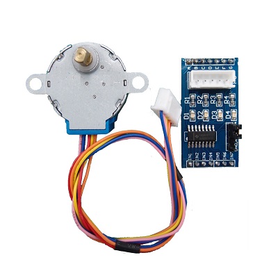
The connection of the dvigun to the Arduinka does not represent labor, since it was sold with a ready-made ULN2003 driver. It was only necessary to provide a separate power supply for 5 volts and a margin of 200-300 mA, because the converter on the arduinka itself is definitely not enough for you. Then on any four digital ports (I took PB1, PB2, PB3, PB4) we transmit the following bit tetrads in the amount of eight pieces.
PORTB=0b00000010;
For rotation in the opposite direction, we transmit the same tetrads, but in the reverse order.
PORTB=0b00010010; PORTB=0b00010000; PORTB=0b00011000; PORTB=0b00001000; PORTB=0b00001100; PORTB=0b00000100; PORTB=0b00000110; PORTB=0b00000010;
The only question that arises is how fast the data is transmitted. It is clear that the more often, the faster the motor shaft will rotate, but to what extent? In the description there is a mysterious frequency of 100 Hz, but what exactly does it imply - a full cycle period or each nibble separately?
In the course of the experiments, it turned out that apparently, it was the frequency of changing the tetrads that was meant. As much as possible I managed to accelerate this frequency to 147 Hz, at which the motor shaft turned around in about a second or two. I didn’t precisely measure it, but you can judge for yourself that this model with this gearbox is no different with special playfulness. But for my beater, it seems, in principle, fit.
But after all, not only speed (or rather, not even very important) is important to us, but how much the force with which the engine can act on the working body. In posts dedicated to this engine, it was stated that they say, you can’t stop it. As it turned out, the shaft itself, yes, you will not stop it, but already a small lever (and I decided to use a lever system) literally 10 cm long, stops and very simply slips even with a small local impact.
Therefore, the initial simplest option, when the lever bolted to the shaft pushes the beater on the hanger, which accordingly batters the bowl, did not pass. The sound was too weak. Therefore, I decided to call for help gravity (the very “heartless bitch” in the words of Sheldon Cooper). In this embodiment, the lever pulled the beater up to an angle of about 30 degrees relative to the direction to the center of the Earth, and then disengaged with it and sent it to the path to the bowl. He received the sound very much, both to me and my neighbors from below. The tripping mechanism was made on a magnet mounted on the end of the lever. As it rose, gravity defeated the magnet and the lock unlocked. Then I made a helping mechanical stop - a transverse bar, with which the beater met near the extreme point of ascent. The engine continued to rotate, the lever pulled and forcibly disengaged the magnetic lock. Here gravity helped the engine, so the effort for disengagement required very little.
The construction itself was assembled on the basis of the details of the children's designer Eiffel Tower. I bought it for a long time and periodically used its parts for my own handicrafts. The tower, of course, was not Eiffel, but in my opinion it is not worse :)
Everything worked fine, but with a single minus - the sound was always the same power. This is normal for the repulse of time, but in the free mode I would like to hear not only pauses of different time, but also sounds of different strength. Therefore, it was necessary to use an electromagnet, which was also very useful. Ordinary magnets also came in handy - I used a column of five small magnets as a damper to tame the vibrations of the beater after hitting the bowl.
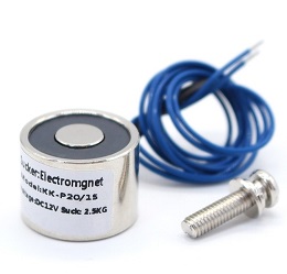
At first I installed it at the end of the lever, but the design turned out to be cumbersome, flimsy and unreliable. Therefore, the electromagnet moved to the beater. It consumed about 300 mA and naturally, it was impossible to control it from the port of Arduino. It was necessary to place a simple transistor key on a small breadboard.

R1 - 560 Ohm, VD1 - 1N4007, VT1 - BD139
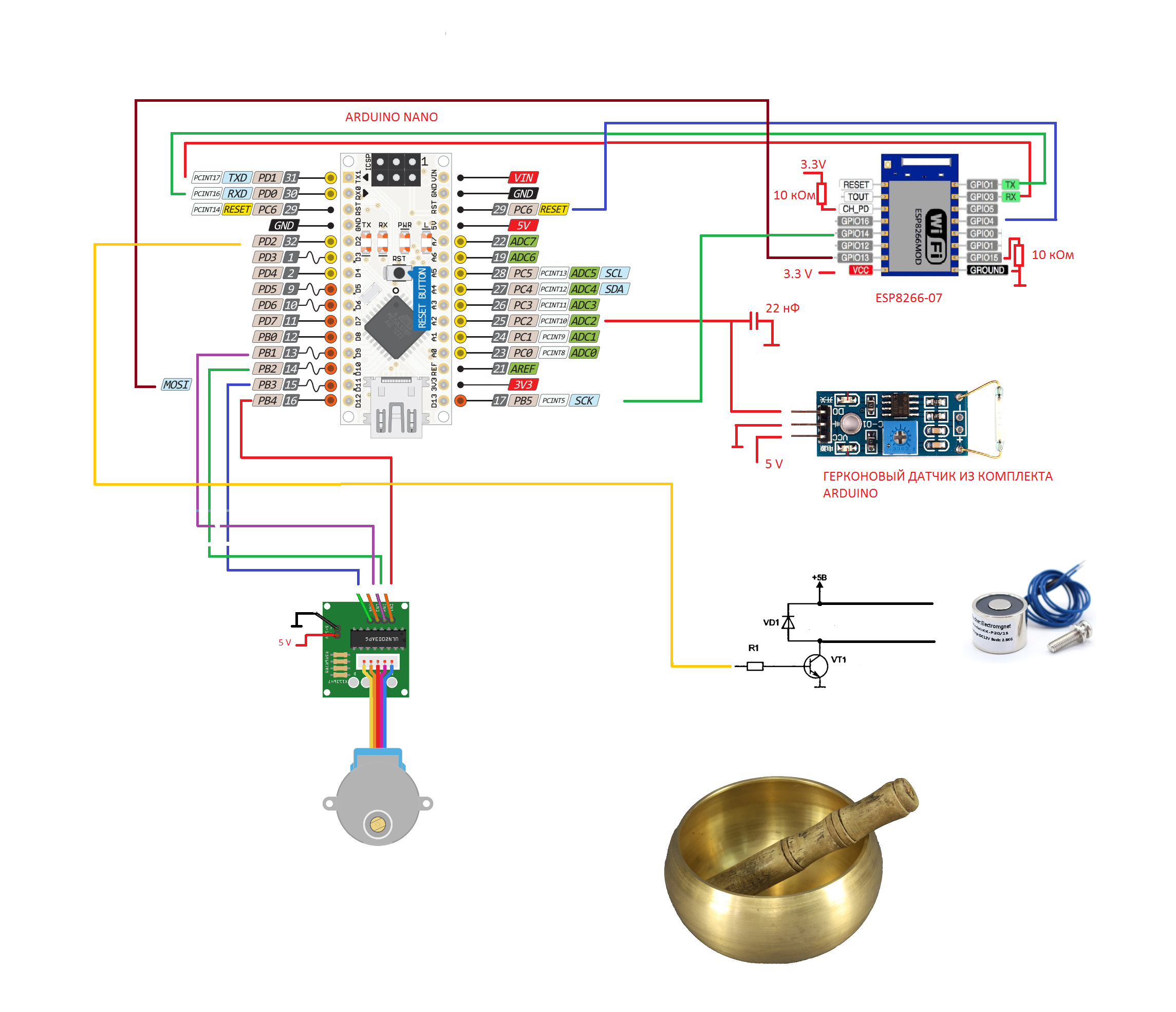
I assembled the main electronic part on the Arduino ProMini and the ESP8266-07 module, the firmware of which I performed completely step by step according to my
old article . As a result, I, as usual, had the opportunity to program the Arduinka over the wireless channel and also communicate with it remotely, exchanging data, which I ended up successfully using. The diagram shows, however, “Arduino Nano” for historical reasons, but its connection is no different.
So, what I wanted and then embodied in the program code.
- When turned on, the system should switch to clock mode.
- On the computer (smartphone) should be an application to change the modes of operation and transfer the necessary data.
- Modes should be simple - clock, random boom and manual control.
I started, as it seemed, from the simplest - hours. Indeed, any novice radio amateur first collects the probe, and then the electronic clock. And then, it is true, one wonders why this watch is one minute behind the hour - it’s supposedly theoretically calculated everything correctly.
I already had a digital clock.
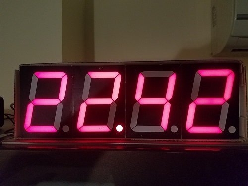
And their main feature useful to me now was their ability to carry exact time from NTP servers using the same ESP8266 microcircuit, represented by its very first and simple incarnation.
I even wanted to write down an article on this topic a couple of years ago, but, having looked at how many times this has already been done, I changed my mind. They will laugh. But in the context of this post analysis of their work is appropriate. As I mentioned earlier in articles, I write programs for ESP8266 in LUA. It happened.
Therefore, the code loaded into that ESP module was this. uart.setup(0,9600,8,0,1,0) timezone = 3
The point is simple. Once (or not), the function founds a UDP client that calls the time server and asks for the exact time accordingly. In response, the server dumps thirty-two bytes, from which it is necessary to extract the required four bytes of data. Unfortunately, this sought-after is not minutes and hours, but the number of seconds that have elapsed so far from January 1, 1900. Therefore, then you will have to calculate the current time from the four bytes of these seconds by various complex manipulations.
Further, everything is easier. Start the UART transmitter and throw the calculated time in three bytes into it - hours, minutes and seconds.
And I again inserted this code, already in my LUA bootloader (link), just at the place where the connection to the WI-FI network has already been made, but further work has not yet begun.
In full, it looks like this. function InstrProgrammingEnable ()
Of course, this goes against my concept, where the ESP8266 is a pure wireless bridge, and the ATMEL microcontroller is everything else, but as they say: “once, not n ...”.
So, we received the initial exact time (directly from the NTP server or indirectly through the application on the computer, it does not matter), then I would like to consider the time to be our own. Firstly, there is nothing to load the network, and secondly, ATMEL theoretically allows counting seconds with good accuracy. Theoretically, yes. But in practice, there are pitfalls.
A small digression about the real-time clock on the AVR.In theory, building a clock on an AVR microcontroller is no big deal. The most rabid designers even shove for this in the circuit of a quartz clock at 32768 Hz. But in fact, this is not necessary. Essentially, a quartz clock is needed in order to multiply a second to form an interrupt and wake a
sleeping (note) microcontroller. If your device works all the time, and the clock usually does just that, then adding extra quartz to the existing one and taking two I / O legs under it is reckless. It is quite possible to use a quartz resonator, which is already there, at eight there or sixteen megahertz. Its quantization accuracy is enough for your eyes, and counting one second with a timer-counter will also be easy.
In fact, the AVR microcontroller already has everything for that. As is known, the input clock signal (say, 8 MHz) is fed inside the chip (say AVRmega328P as the most running signal for arduinks) to the so-called predecessor, where it can be further divided (usually by 8, 64, 256, 1024). And then he arrives at some timer counter (say T1), which begins to increment immediately.
So, take 8 MHz and divide by 256. We respectively receive the clocking frequency of the counter 31250 Hz. Accordingly, since the T1 counter is 16-bit and can count up to 65535, respectively, then it will just have time to calculate up to 31,250 in one second. What we need. In addition, our timer has another very useful comparison register. If we write down the number 31250 there, then under certain conditions it will be constantly compared with the contents of the T1 counter, and finally, when it becomes equal, the counter will give an interrupt signal, they say, hold your second.
It turns out convenient, but, unfortunately, not entirely accurate. For our counter will count with a quantization error of 256/8 000 000, which gives a rather large calculation error of one second in as much as 32 microseconds. And this leads to an error of 2.8 seconds per day (0.000032 * 3600 * 24).
But if we divide the original 8 MHz by a smaller value, for example, 64, then the quantization accuracy will increase 4 times to 8 μs and reduce the total error to 0.33 seconds per day. But, unfortunately, in this case, the counter will need to count up to 125,000, and such a number in sixteen bit register will not enter. We'll have to write a smaller number in the comparison register (62500 still holds)) and add a loop in the program itself, where one second will be considered not one by one, but by two interrupts.
But we took the perfect case, and the real quartz resonator, especially mounted on the “made in China” board, can bring you many surprises. No, in general, if you look at standard quartz on
datasheets , then theoretically, not everything is so bad.
As we can see, the quartz of the middle price category behaves quite decently. It has an instability of its own tuning of 25 ppm (or in other words, 25 parts per million), that is, it will resonate at a frequency of not 8 MHz, but, for example, at a frequency of 8, 0002 MHz, which will give us as much as 2.1 seconds of error per day. But this is a constant error and can be taken into account. Such quartz can also float at a temperature of 5-10 ppm per degree, but under room conditions of the device, the error will also be small. There is also such a factor as aging, but it is quite scanty and changes the characteristics of quartz to the state of at least some noticeable, well, maybe five years. Or ten.
And here we are joyful take some Chinese clone Arduino, for example ARDUINO UNO.
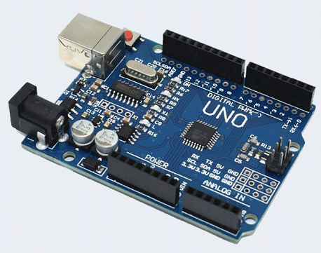
We start on it a test program of calculation of time and opupey. Lagging at one minute? Easy! Second Arduino UNO board? Not any better.
Take the Arduino ProMini.

And here it is better, yes. The error has decreased to twenty seconds per hour. Well, already comparable to a mechanical clock with a cuckoo.
The last board that I had on hand was the Arduino Nano.
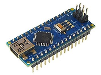
And she only showed more or less sane results.
But even with such a board, using only theoretical constructions, you understand, you cannot make accurate clocks. The board must be tuned and I, with a sigh, climbed behind the oscilloscope.
As it turned out, the Arduino boards have an unpleasant feature - the output to which the quartz resonator is connected does not have access to a comb of outputs, although it corresponds to the PB7 port. Like, if the port is busy for quartz, then you are not sure to cling to it. And just to the foot of the microcontroller is very difficult to pick up the oscilloscope probe, for surface mounting and 0.5 mm pitch between the terminals. But even joining the right leg gave me nothing. Either because I poked incorrectly, or poked at all the wrong way, because the output of the quartz resonator may not be the output of the clock generator at all, and in general, it is inside the microcontroller itself. Therefore, we had to go through workarounds — put a prescaler on the minimum division factor — one, write zero in the comparison register so that the interrupt jerked right away and put the microcontroller into a special mode in which the pin of port PB1 changes its logical state with each such interruption.
Logically, when you turn on the Arduino Nano 16 MHz board, a 8 MHz square wave should appear at the output of this port.
What happened. The oscilloscope showed a frequency of 8. 002 31 MHz. Moreover, the last digit lived its own life and I still did not understand, either the lack of accuracy of the oscilloscope, or the frequency of the crystal oscillator floats like this. More like the second.
There, too, there was no good thermal stability. If you breathe on the board (maybe, by the way, the containers are still moving from the humidity?) Or bring (from afar) a soldering iron, then quartz could drive off immediately to fifty hertz. And these measurements are still grossly halved, since the original frequency is 16 MHz.
Thus, in Arduino boards (at least those of Chinese origin), it is impossible to achieve an accuracy of more than 200 Hz at a clock frequency of 16 MHz. This gives us the extreme accuracy of the clocks collected on such boards no more than one second per day. And this is still good.
Because there are Chinese clones Arduino UNO, already mentioned by me earlier, with which, in general, everything is bad. And they are very common, because cheap and convenient.
So, their frequency may differ from that declared by more than a hundred kilohertz! That even for the worst Chinese quartz is somehow uncharacteristic.
The riddle begins with the fact that 12 MHz is written on the quartz itself! And in sales descriptions too.
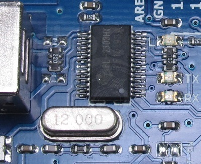
But there is not 12 MHz, that's for sure. If you enable the UART serial port on the board, you will see for yourself. Since the UART tuned to this frequency will not work for you. And tuned to the frequency of 16 MHz - will be. Moreover, I personally watched the oscillograms on both of my Arduino Uno boards. The first board had a generator frequency of 15.8784 MHz, and the second one had 15.8661 MHz.
But then suddenly it turned out that 12 MHz quartz is not directly related to the AVR microcontroller, but is designed to work the serial port with a computer via USB (to download sketches). Therefore, the assumption that there is no quartz inside, but a poorly tuned RC-chain was not justified. And the quartz we need is much smaller and is located next to the microcontroller chip. But it is very small and there are no inscriptions on it.
As a result, I could not understand how and where you can find quartz resonators of such a perilous quality. But apparently, everything is possible in China.
And somehow I thought about brave men using arduinka for serious cases. Okay, software can and should even be written by yourself, but what to do with the quality of the modules themselves? Apparently, from the electronic components, the Chinese shove them all the cheapest and rejected.The program "Singing Bowl" for AVR.In the end, defeating all the difficulties with the exact calculation of time, I wrote the following code for my Arduino ProMiniC program for microcontroller AVRmega328P #define F_CPU 8000000 #include <avr/io.h> #include <avr/interrupt.h> #include <stdint.h>// #include <math.h> // #include <stdio.h> // - #include <avr/eeprom.h> #include <stdbool.h> #include <setjmp.h> #include <stdlib.h> volatile bool change_mode = false; volatile bool boom =false; volatile bool go_ahead=true; volatile bool go_back=false; volatile bool gerkon=false; volatile uint8_t latency=2;// latency = 1 volatile uint8_t hour=12; volatile uint8_t hour24=12;// 12 volatile uint8_t minute=0; volatile uint8_t secund=0; volatile uint8_t power=0; volatile uint8_t pause_between_boom=0; volatile uint8_t first_byte=0; volatile uint8_t second_byte=0; volatile uint8_t third_byte=0; volatile uint8_t firth_byte=0; volatile uint8_t fifth_byte=0; volatile uint8_t cSREG; ISR(USART_RX_vect) { // , // – , . if (first_byte==0) { first_byte=UDR0; change_mode=true; goto ret; } if (second_byte==0) { second_byte=UDR0; goto ret; } if (third_byte==0) { third_byte=UDR0; goto ret; } if (firth_byte==0) { firth_byte=UDR0; goto ret; } if (fifth_byte==0) { fifth_byte=UDR0; goto ret; } cSREG=UDR0; ret: return; } ISR(PCINT1_vect )//PC2 int 10 // { if (go_ahead) { UDR0=44; // 44 } if (go_back) { gerkon=true; } } ISR(TIMER1_COMPA_vect) { // secund++; if (secund ==60) { secund=0; minute++; if(minute==60) { minute=0; hour++; if(hour==12) { hour=1;// 12 } hour24++; if(hour24==24) { hour24=1; } boom=true; } } } void time_delay(long dell)// { long i; dell=dell*796;// 8 for(i=0;i<dell;i++){;;}; sei();// , - .WTF ?????????????????????? } void turn_onkward()// { uint8_t legnth=170;// ( 0 170) for(uint16_t i =0;i<=legnth;i++) { go_ahead=true; PORTB=0b00000010;// time_delay(latency); PORTB=0b00000110; time_delay(latency); PORTB=0b00000100; time_delay(latency); PORTB=0b00001100; time_delay(latency); PORTB=0b00001000; time_delay(latency); PORTB=0b00011000; time_delay(latency); PORTB=0b00010000; time_delay(latency); PORTB=0b00010010; time_delay(latency); if (i>140) { PORTD |=(1<<PORTD2);// , 1 - } } time_delay(100); go_ahead=false; } void turn_backward(uint8_t pause, uint8_t force_of_sound)// // // { uint8_t legnth=170;// ( 0 170) for(uint16_t i =0;i<=legnth;i++) { go_back=true; PORTB=0b00010010; time_delay(latency); PORTB=0b00010000; time_delay(latency); PORTB=0b00011000; time_delay(latency); PORTB=0b00001000; time_delay(latency); PORTB=0b00001100; time_delay(latency); PORTB=0b00000100; time_delay(latency); PORTB=0b00000110; time_delay(latency); PORTB=0b00000010;//16 ms , latency = 2 time_delay(latency); if (i==force_of_sound*17) { PORTD &=~(1<<PORTD2);// , 0 - } if (gerkon) { gerkon=false; break; } } time_delay(50); time_delay(pause*1000);// go_back=false; } void sound(uint8_t force,uint8_t pause) // 1 10 { turn_onkward(); turn_backward(pause,force); } int main(void) { sei(); // UART 9600 8 time_delay(2000);// , esp - UCSR0A=0; UCSR0B=0b10011000;// a UART UCSR0C=0b00000110; UBRR0L=51;// 8 9600 UART UBRR0H=0; // INT0 2 10 // PCICR|=(1<<PCIE1);// 14-8 PCMSK1|=(1<<PCINT10);// INT10 DDRC&=~(1<<PORTC2); DDRB=0b00111110;//PB1-PB4 , PB5 DDRD=0b00000100; // PD2 //SET INTERRUPT FROM TIMER1 AND SET TIMER1 GTCCR=0;//RESET PRESCALER TCCR1A=0;//I/O NORMAL WORK TCCR1C=0; TCCR1B=0B00001100;//1/256 PRESCALING AND CTC MODE TCNT1H=0;//RESET TIMER1 TCNT1L=0; TIMSK1=0B00000010;//SET COMPARE A INTERRUPT ENABLED OCR1AH=0x79;//SET TIME CONSTANT IN COMPARE REGISTER OCR1AL=0xa7;// 31143 7 972 608 TCCR0B=0b00000010;// 8 0 255 while (1) { begining: time_delay(1000); if (first_byte!=0) { UDR0=first_byte;// . (100,101,102) } if (first_byte==100)// ( NTP { hour=second_byte;// if (hour>12)// 12 (24 ) { hour=hour-12; } if (hour==0) { hour=12; } minute=third_byte;// secund=firth_byte;// power=fifth_byte;// first_byte=0;// second_byte=0; third_byte=0; firth_byte=0; fifth_byte=0; change_mode=false; goto clock_mode; } if (first_byte==101)// { power=second_byte; pause_between_boom=third_byte; first_byte=0; second_byte=0; third_byte=0; firth_byte=0; fifth_byte=0; change_mode=false; goto random_mode; } if (first_byte==102)// { power=second_byte; first_byte=0; second_byte=0; third_byte=0; firth_byte=0; fifth_byte=0; change_mode=false; goto hand_mode; } // , first_byte=0; second_byte=0; third_byte=0; firth_byte=0; fifth_byte=0; goto begining; clock_mode: while(change_mode==false) { if (boom)// { for(uint8_t i =0;i<hour;i++) { if ((hour24>21)|(hour24<10))// { sound(3,0);// 10 (), 0 boom=false; } else { sound(power,0);// 10 (), 0 boom=false; } } } } goto begining; random_mode: while(change_mode==false) { uint8_t random_power = TCNT0;// 1 uint8_t random_pause = TCNT1L;// 1 random_pause=TCNT0;// 1 random_power=random_power/25; if (random_power<5) { random_power=random_power+2;// } random_pause=(random_pause/25)+pause_between_boom; UDR0=random_pause; time_delay(100); sound(random_power,random_pause); } goto begining; hand_mode: sound(power,0); goto begining; } }
Everything works simply. After the initialization of the periphery, the microcontroller goes into an infinite loop, waiting for a command on the UART. The command codes are as follows:100 clockmode 101 randommode 102 manual mode.Since the AVR doesn’t care where the command is coming from, the command from ESP8266 is triggered first after switching on. As already mentioned, the ESP module clings to the network, drags the exact time from the NTP server from there and sends it to the microcontroller. Thus, at first, Arduinka enters the clock repulse mode. By interrupting the T1 timer, the seconds, minutes and hours are counted and, if necessary, functions are called to drive the stepping motor back and forth in order to beat the time.An interruption from the reed switch sets the same zero point, if over time the lever pulling the beater starts to move relative to the motor shaft.Computer application.It is still based on the same old programs , only the visual presentation changes here.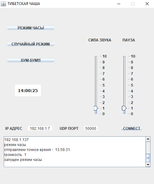 Everything is also rising communication channel with AVR via HTTP and UDP connections. Then, if necessary, the necessary control command and related data are sent in the form of UDP packets. Of course, it would be better to separate the control and data through different channels, but, firstly, for this you need to edit the LUA code in the loader, and secondly, there is no point in this, because the microcontroller and the commands and data come in one and the same UART. And yes, sometimes (rarely) AVR confuses them. But this is not scary, because if the microcontroller does not recognize the command, then it will not execute it, and even joke about the application on the computer, which in turn will prompt you to repeat the input.The code is available on Github.P.SIn general, Tibetan monks not only beat peppers on singing bowls. If you gently drive the beater just on the rim of the bowl, then without any knocking a wonderful sound will be born, having under it the
 divine nature of resonance. But this is for Arduino a really serious challenge.