Hello!
Today I would like to tell you about our new piece of hardware based on the Raspberry Pi Compute Module, designed to study computer vision and installation on robots and drones. In fact, this is a “smart” stereo camera - it supports work with two cameras at the same time, has real raspberries as a “heart” and, most importantly, works with the stock version of Raspbian.
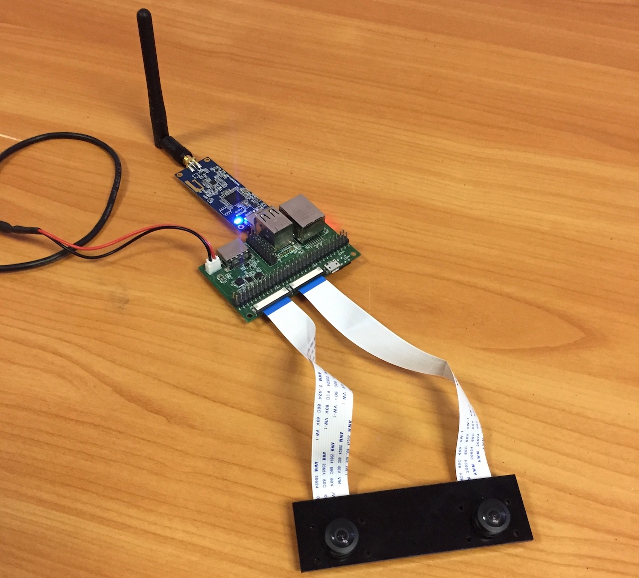
Here is what the assembled solution looks like, with two cameras installed and a Pi Compute module.

The device works with the stock version of Raspbian. You only need to copy our dtblob.bin file in order to enable support for two cameras.
This means that you can use the usual raspivid, raspistill and other utilities for working with images and video.
For reference, support for stereo mode appeared in Raspbian already in 2014, simultaneously with the release of the first version of the Raspberry Pi Compute. You can see the development history of stereo support
on the Raspberry forum.Before describing the technical details, let me show you some real examples of how the device works.
1. Image Capture
Code:
raspistill -3d sbs -w 1280 -h 480 -o 1.jpg
and you get the following:
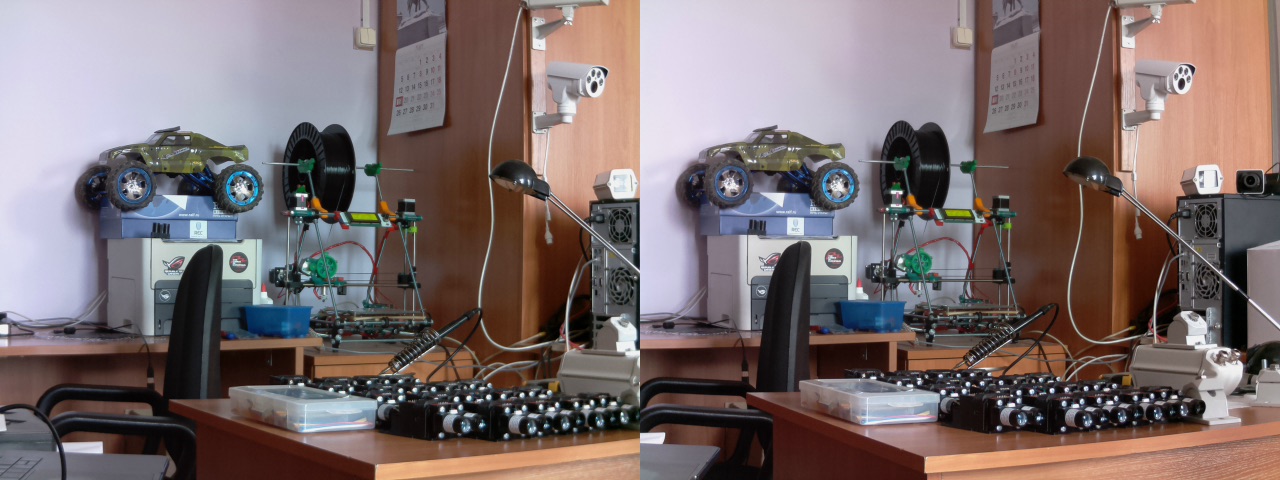
You can download the original captured image
here .
2. Video Capture
Code:
raspivid -3d sbs -w 1280 -h 480 -o 1.h264
and you get the following:
You can download the original video file (converted to mp4)
via this link .
3. Using Python and OpenCV to build a depth map
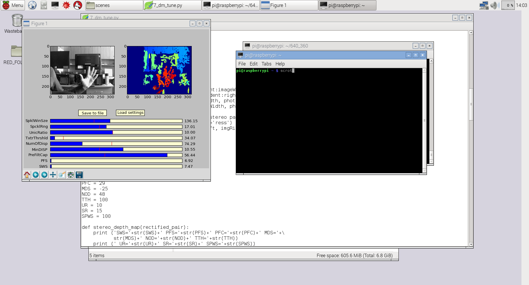
In this case, I used a slightly modified code from the previous 3Dberry project (
https://github.com/realizator/3dberry-turorial ).
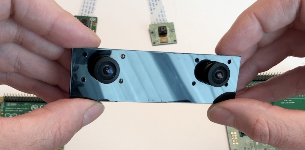
To get these pictures and videos, we used just such a pair of cameras:
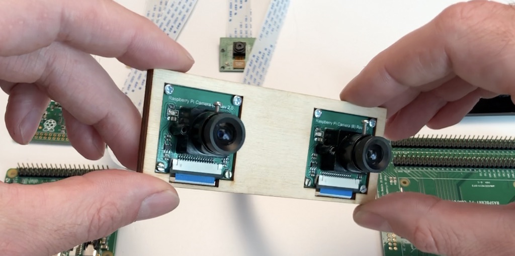
For installation on drones, we often use wide-angle (160 degrees), these are:
Now a little more about the piece of iron itself
Technical details
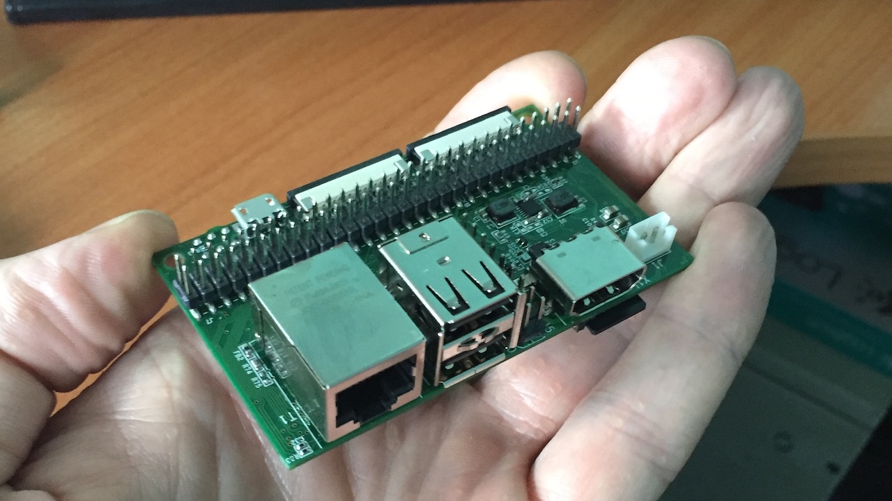
Front view:
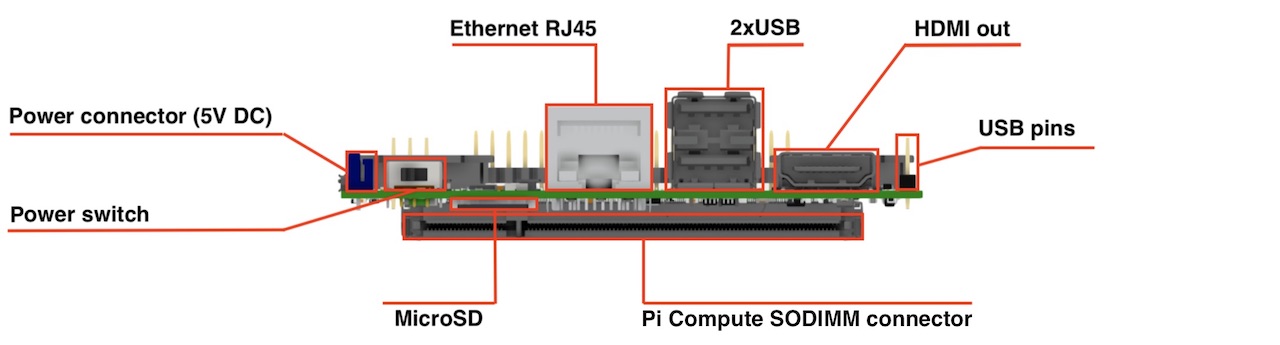
View from above:
 Main characteristics:Dimensions:
 90x40 mm
Camera: 2 x CSI 15 lanes cable
GPIO: 40 classic Raspberry PI GPIO
USB: 2 x USB type A, 1 USB on a pins
Ethernet: RJ45
Memory: Micro SD (for CM3 Lite), the rest of the NAND (flash)
Monitor: HDMI out
Power supply: 5V DC
Supported raspberries: Raspberry Pi Compute Module 3, Raspberry Pi CM 3 Lite, Raspberry Pi CM 1
Supported camera types: Raspberry Pi camera OV5647, Raspberry Pi camera Sony IMX 219, HDMI In (single mode)
For NAND firmware: MicroUSB connector
Power Switch: Yes, yes, this is it. No more microUSB plug-in wires for power supply reboot!
Little history
In general, the idea itself appeared in 2015. The first version was born at the end of 2015. Some people know that our team has a “fad” on remote control of various mechanical gizmos, so in the first release an additional chip was installed on board, which gave us 16 PWM outputs - for taxiing servos, motors and other usefulness.
By the time the market was only the first version of the Compute module, which was carrying the old processor from the very first processor. Zhelezka did an excellent job with capture, compression and streaming video, but in the end we rested on the processor. For example, it was not enough for both the h264 stream to the pilot and the RTMP stream to the server at the same time. And for robot builders, the basic Wishlist was the construction of a space map using a depth map and SLAM - there was not enough processor at all.
Here on you - the version of Compute Module 3 comes out. They immediately "jumped" from the first version to the third, putting the processor from the third Raspberry. Now his power was enough to cheat something on the fly.
However, it turned out that generations seem to be compatible, and also not very. The fact that Compute Module 3 was a millimeter wider did not bother us. But the requirements for nutrition have seriously changed.
In addition, we have already collected comments on the results of the work with the first version, and we decided to release a new one, in which we made all the changes that had been accumulated.
What is fixed in the second generation
Added support for Compute Module 3We have a switchable power scheme, so if you want, you can work with the first raspberry. The choice here is simple: if you only need to broadcast the video, the first raspberry is perfectly enough. As a bonus, it is almost three times less power consumption and heat dissipation. And you need to find something more serious (several videos or computer vision) - we put the third one.
Deployed the module "chips from the board"In the first version, the type of SoDIMM connector on the board was confused, as a result the computer-module got up with chips “to mother”. On Compute Module 1, this didn’t cause any problems - the percent was warming up weakly, and there was enough of a bottleneck between the boards for normal cooling. With the third, such a trick would not have rolled, so we “turned” the connector, which resulted in the re-routing of the entire board from scratch.
Regular MicroSD supportThe first computer-module by default had a built-in flash on board and could not work with microsd. We tried to hang MicroSD there as a second drive, but we ran into a big bunt in support of it. Communication with kernels on the crimson forum showed that the problem is not easy (when loading the module, I randomly chose NAND or MicroSD for the boot). As a result, on the current revision, we made the layout as the reference devboard from the raspberry. If Compute Module
Lite - without built-in NAND - we work with microsd as in usual raspberry. If the version is not Lite or the first module - microsd is not available.
We moved the camera connectors up and smashed to 65 mmIn the first version of the connectors were directed along the plane of the board. Trifle, but after many installations in the case revealed several problems.
- A camera plume sticks out of the connectors, which is desirable not to bend (especially the blue reinforced part). This stupidly took unnecessary space in the case and interfered with the installation.
- Connectors were very close - it made it difficult to work with loops.
- The cameras in the case usually stand on a 65 mm stereo base, and the cables on the board were close by. It turns out that each cable had to bend unnaturally - breaks, breaks, popping out of the connectors.
Removed chip and additional 16 PWMAfter analyzing many recent projects, they realized that this feature is irrelevant. Most often there is enough software raspberry PWM.
Added power switchThose who have worked a little with raspberries understand what it is about :-)
Added a third USB on the side pinsIn our crimson projects, we often need USB dongles on board. If they are stuck into the connectors on the board, we have a module sticking far out. Attempting to use a USB extension cable further exacerbates the problem. There was only one option - soldering wires directly to the raspberry. The side pins we added allow us to make a simple extension cable and place a USB dongle (usually WiFi or 4G) right along the board, and all this equipment fits perfectly into a compact case.
This is the story I wanted to tell you today. Thank you for your attention and ready to answer questions.