
The idea of e-led me up for a dozen years, realized just now!
Spoiler
The indicated amount is funds for the motorization of an ordinary bicycle, including batteries.
The task is to maintain the speed on a horizontal stretch of asphalt 20 km / h and help in other cases.
Power reserve - ~ 30 minutes
Let's get started
To begin, let me explain why $ 50 - the limit cost of homemade - is the price of a Chinese chainsaw, the engine from which you can prikolhozit, and $ 200 - already Honda Dio27.
Introductory were the following:
- On a horizontal stretch of asphalt, a cyclist on a road builder spends 100 W to maintain a speed of 20 km / h.
- Most power is needed only briefly on accelerations / rises.
- The voltage of the lead (12V) battery sags heavily under load, in e-velas up to 10V (and the power, proportional to the square of the voltage, drops twice (versus 14V)!)
That is, for normal cycling, it is enough to nominally give up the engine with 100W of power - you just need to get rid of the voltage drop!
This is implemented by a PWM control of the power supply of a 12-volt motor from a 24-volt battery, plus the possibility of realizing a short-lived FORSAGE.
As a result, the General Motors cooling radiator engine (Daewoo AKA Opel Kadett) ~ 150W was taken (consumption - at the output just Over100W is) $ 13.
And the two most popular batteries for bespereboynikov - AGM, 12Volt, 7amper-hours each, for $ 10.
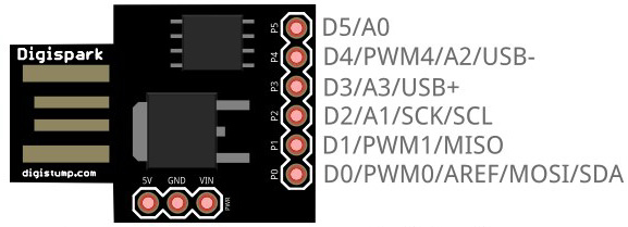
If you take another price Digispark - $ 2
In general, plus $ 1 - transistors (2pcs - IRLZ44NPBF) - I got $ 36, but let's say someone does not have plywood, a cartridge from an old drill and copper wires with a cross section of 2.5 square.
All this is bought in the "flea market", and other components can be used - the engine, batteries.
I promised myself that at the beginning of the summer it would all go - but I did not have time, I went crazy - and it did!

At first, even without a controller, the batteries are charged with a current of ~ 7.5% - 0.5A each, are paralleled and are connected via an ordinary switch to the engine.
Yes, I know - fierce collective farm , but it was necessary to start with something, and you can modify and comb forever.
The basis is the killed Ashanbike on wheels 24 "(there will be Kama / Desna / Salute), well, or the wheels from them on this frame.

Blue duct tape - OUR ALL (of course not the same at all)!
I sealed the vent holes, and was right - the dust on the engine sits a layer thick in a finger!
The engine mount is made of delta-wood (bakelite plywood) and a building metal corner.
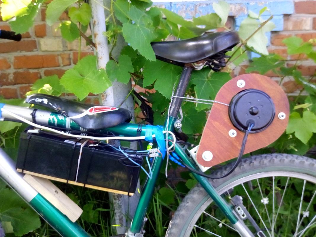
Drive - straight on the tire.
Given the speed under load 2400O / min, for 20km / h the diameter of the roller should be ~ 40mm (the cartridge of a conventional drill). But - the village, primer, limited to twenty millimeters. Yes, and in this version, even on the ground, the speed was kept (~ 10 km / h), there is no question about overclocking.

In general, the test run of the first ten kilometers showed by LUTY the need to increase the engine power at least to the nominal one.
I'm not talking about the efficiency of the transfer to the tire - 70% in the jump.
So, the connection scheme of the controller Digispark (may the reader forgive me for drawing with a pencil on paper).
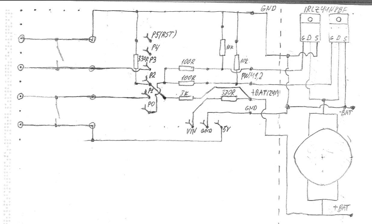
I can imagine what the battle is now on in the Izyum place Yes, yes, yes - I know I did not put the suspenders on the buttons. There were demons resistors, but they self-destruct)
The fact is that as it turned out, not all inputs of the Digispark accept a logical zero, the rest also belong to a logical one.
Schematically, everything is simple — digital input / output pins are any, logical 0 on the 5th reset controller. The reality turned out to be much more confusing - I had to pick it up by typing - in the end I used to pick up the pull-up resistors, put it together to work.
To implement the device, I cut a piece of the breadboard of 10x18 holes (3x5 cm).
Two more buttons were needed for the three modes:
- Button 1 is pressed - the mode corresponding to 12V is 100% - until the batteries are exhausted.
- Button 2 - 15V is pressed - 156% - in principle, there is such a voltage in the on-board car network, but it is better not to use it for longer than 15 minutes.
- Two buttons at once - FORSAGE! 256% - to jerk with a traffic light / from an angry dog, uphill, time - less - better (otherwise burnt windings are guaranteed).
The latter has not yet implemented - I am afraid for the collector brushes and the windings - they even get overcurrent on 1 mode.
The rest - resistors - 2pcs - 10K (tightening the zero on the transistor gates).
3K and 330R - voltage divider to the analog input P2 (when falling to 18V - the load is cut off).
2x100R- transistor control current limiting from the P0M output P0.
Finally, the 330R on the Vin is the Digispark voltage regulator's current limiter (so as not to burn the voltage regulator).
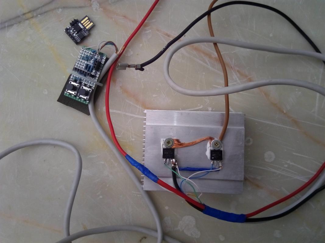
In general, in the hardware, everything looked as follows - the power transistors were attached to the radiator from some processor 70x60x40mm.
The drain IRLZ44 is connected to the heat sink plate, therefore, in order to eliminate the need for isolation of closely spaced legs - the engine was connected here (brown wire).
A few words about transistors - field, 5th generation, with an internal reverse diode (it is important to connect an inductive load, such as: a motor).
Maximum current - 47A, voltage - 55V, Rds (at 5V at the gate and current 25A) - 0.025Ω.
You can choose any other powerful field-users with low transition resistance.
In addition, in order not to use the control driver, MUST be with a logic level control (L in the name).
Why are there two of them? The nominal characteristics of the same resistance are indicated for 25 degrees Celsius and currents of 20-25A, with heating and a higher current will be worse.
And yes, the logical 1 is not always exactly 5 volts, the very same 4V transistor on the gate is not fully open, the Rds is already 0.035 ohms at a current of 21A.
The reserve should be at least double - and through the engine, taking up to 14 Amps at 12 volts, at 24V can flow 28A!
And besides, I have about a dozen of them left - it is better to immediately put a pair, than to re-solder one at a time.
I completely forgot, I turn on Digispark in plugs (PBS PBD).
Now - sketch:
// Digispark (Attiny85) // - byte voltage1=0; byte pwm0=0; void setup() { // // MOSFET pinMode(0, OUTPUT); // pinMode(2, INPUT); // pinMode(1, INPUT); pinMode(3, INPUT); } void loop() { analogWrite(0,0); delay(1); voltage1 = analogRead(1)*62/1023; // - 18 - if ( voltage1<18 ) { goto lowvoltage1; } if ( digitalRead(3) ) { if ( digitalRead(1) ) { // - 12 pwm0=(12^2/voltage1^2)*255; analogWrite(0,pwm0); delay(100); } } else { // - 15 pwm0=(15^2/voltage1^2)*255; analogWrite(0,pwm0); delay(100); } lowvoltage1: ; }
What can be changed in the scheme and components?
Engine - originally intended to use the ME-272 (VAZ), but the Korean turned out to be more accessible, if you take the engine for disassembly, you can save on additional batteries.
Batteries - in terms of price-capacity ratio (in ampere hours) 12-volt for 7Ah - are optimal, 2 batteries per 10Ah will cost FOUR sevens! If you need to increase mileage - connect them in pairs in parallel! And yes - no gel - only AGM!
Impressions:
The test run of the first kilometer on a more powerful mode showed no overheating of the engine (up to 40 degrees Celsius) and a slightly warm transistor radiator - it means the circuit works correctly.
At rest - consumption - 30mA - purely Digispark, there are no leaks through the MOSFET.
For the selected type of drive need tires-slicks.
But even with such a scenario, the engine pulls more merrily than from parallel-mounted batteries directly - along the asphalt section, even with a "breeze."
In general, the idea of a PWM control of a 12-volt motor from a 24V source was justified!
With you was Andrew, to new meetings on Habré!