Good afternoon, dear habrazhiteli!
My name is Mikhail Matveev, and I would like to bring to your attention the project of a modern “radio designer” based on the Atmega328 MK and the RDA5807M chip.
Prehistory
I think many of you have not only heard, but also directly encountered such a platform as Arduino. And as shown by my personal statistics, very few go further than blinking LEDs. When I first met Arduino for the first time, I was stopped by the fact that there were no ideas how exactly I could use all the possibilities of the same UNO to the fullest. Enough only to build a simple robot on two wheels and alarm. At the same time, I wanted to do something more solid.
Then I remembered my childhood, in which there were so-called "radio designers". Severe Soviet DIY Kit, which, with proper assembly and proper soldering, even began to work, and caught radio stations in various bands: Youth, Electron-M, and others.
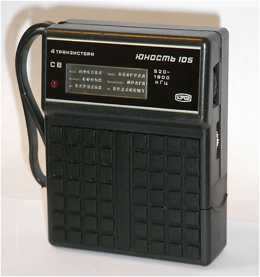
I did not get any of these Kits, but I got EKON-1:

The main "chip" of this designer was that with it you could quickly and easily assemble a large number of different devices, from simple "tweeters" to a fully-fledged radio receiver.
EKON-1 is one of the many reasons why I ended up in the field of IT. And it occurred to me that it would be nice to create a modern version of such a designer, so that everyone could enjoy the device that they just assembled with their own hands.
Prototype on circuit board
My friend, a talented engineer Konstantin Tomarevsky, supported the idea, and we began to think about how to make the first prototype.
The idea was to create an FM receiver that could be controlled via the MC.
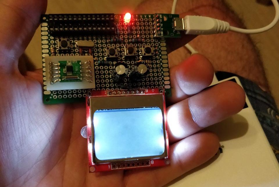
The first prototype was assembled on a montage, and it became clear that it works :)

For the very first version, the following components were selected:
1. MK Atmega328P-PU
2. RDA5807M
3. Display Nokia 5110
This microcontroller is used in the Arduino UNO, respectively, our device is compatible with UNO at the hardware level.
RDA5807M - "heart" of our designer. This tuner has the following features:
- CMOS technology
- Monolithic case, does not require external components (almost)
- Bandwidth: 50-115 MHz
- Channel spacing - from 200 to 25 kHz
- RDS / RBDS
- ADC and built-in frequency synthesizer
- Adaptive noise reduction
- Digital Interface (I2C)
- Signal level (RSSI)
- Amplifier
- Adjust the sound volume
Nokia display - black and white, 84x48 pixels. It is very easy to connect and manage.
After soldering on the circuit board, it turned out somehow like this:
It was decided to use the Arduino Bootloader, it allowed to maintain compatibility with all the numerous libraries and significantly reduce the entry threshold for those who already had any experience with the platform.
The user interface is implemented as follows. Three buttons connected to the analog input of the MK via resistors are used to switch modes and control the receiver. Another button is used to reset the MK. The screen, respectively, displays information about the volume, station, etc.
LUT, photoresist and debug
After successful tests on the circuit board, we decided to create several more prototypes using the LUT method (and later on using a photoresist). We also decided to improve the receiver by adding another sound amplifier to connect not only headphones, but also an external speaker. The choice fell on the PAM8403, this is a simple and inexpensive amplifier that requires 5V power supply.
The first prototype, produced by the LUT method, looked as follows:

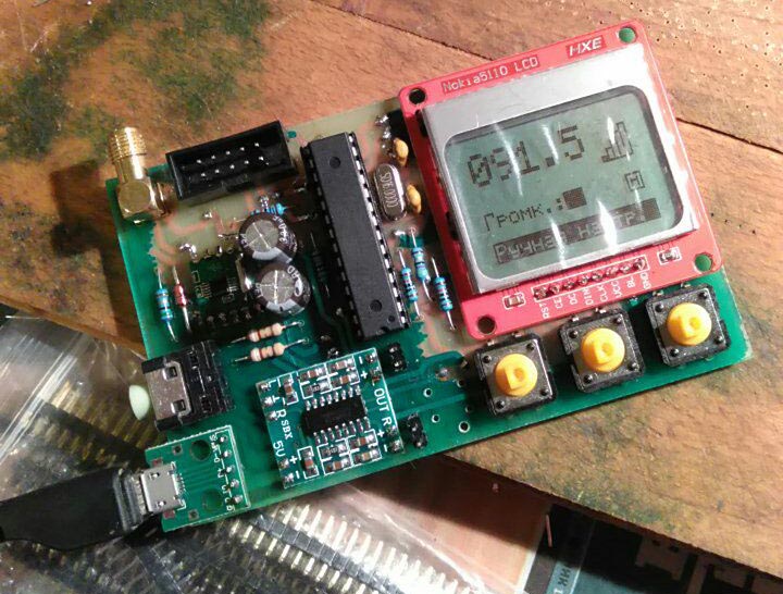
LUT is a good thing for relatively fast prototyping at home, but when it comes to double-sided boards, complexity begins. The number of components on the board increased - for example, we decided to place a connector for the programmer on the board, so that there was no need to extract the MC for flashing every time. So, the subsequent prototype became two-sided, was made by photoresist and began to look much nicer:

In the assembly:
The next step was the rejection of the “mounted” components, which we placed on the board using single-row PINs. So, it was decided to replace the amplifier on the LM386N, install the level converter CD4050BE. All this complicated the design, but the device began to look much better.
The final prototype, made by us at home, looked like this:

PCB order
In China, you can order printed circuit boards made by industrial means. The cost is relatively small, even with small runs, and the waiting time (including delivery) usually does not exceed 2-3 weeks.
The first "batch" of boards ordered on PCBWay. So she looked:

One of the problems that we have encountered due to inexperience: metallization "eats" a significant part of the size of the hole itself, so some components hardly "got into" the right holes. When designing a scheme, it is necessary to consider this point.
According to the test results, we have further refined the design, adding a few capacitors for more stable operation of the device. Collected another prototype:

USB connector is used to power the receiver. Power is also supplied when the programmer is connected.
Everything is working!
Firmware
Separately worth staying on the firmware. It is written in C ++ and we distribute it under the GPLv3 license:
https://github.com/xtremespb/fm_receiver. I practically did not develop in C / C ++, so (probably) the code is far from ideal and may contain errors, but the GPL does and the GPL so that you can refine it with the community :)
Current firmware features include:
- Manual and automatic tuning stations
- RDS
- Volume control
- Enabling enhanced bass mode
- Enable or disable the display backlight
- Display and dynamic visualization of the signal level
In the next, fourth revision, we will make some more useful "chips": we connect the left and right channels to the analog inputs on the MK, which allows us to "visualize" the incoming audio signal.
By the way, the capabilities of the device are not limited to the radio! No one bothers, for example, to write some game (for the sake of interest, I made the good old Arkanoid) or another program that uses the capabilities of the board.
Production
The development of the device from idea to implementation took about 6 months, which, with an almost complete lack of experience in this field, is not so bad.
At the moment we have about 10 fully assembled kits, which include everything you need to build your own device:
- MK Atmega328P-PU
- Level Converter CD4050BE
- Display Nokia 5110
- Receiver RDA5807M
- USBasp programmer
- Operational amplifier LM386N
- Connectors for MK and programmer
- USB B, Audio Jack 3.5, three buttons, wires, single-row connectors
- 11 resistors and 12 capacitors, 4 inductors, quartz, zener diode and LED
- Speaker
- Printed circuit board
You will need solder, flux and soldering iron for assembly, nothing else is needed.
All components are packed in a small box of crafted cardboard:

Firmware sources are already available on Github; The gerber file, schematic diagram and assembly instructions will also be published later.