Reverse engineering of time relay VL-76-S

Once upon a time I came across an electronic digital time relay VL-76-S, new, in packaging, but out of order. No defects on the printed circuit boards were found inside. So, the factory marriage, broken firmware.


General view of the relay.

What surprised me, is the popular and simple ATTiny2313 microcontroller. Externally, this design consists of a dial in the form of three ten-day switches and a terminal, to which 220V power and the contacts of the executing EM relay are connected. The setting range is 0.1 ... 99.9 min. in 0.1 min steps (6 seconds). On the Internet there are no schemes and firmware for this design, which is not surprising. Without thinking for a long time, I decided to copy the circuit from the printed circuit boards and then write a program on the MK independently.

The design consists of three printed circuit boards interconnected. On the first board, there is a power supply and performing the TRA3 relay. The power supply is made according to a transformerless circuit: quenching capacitors are used to reduce the voltage. On the second board is MK ATTiny2313 and other auxiliary elements. On the third board there are switches (actuators) and a control LED.


Photo of the third board on the reverse side.

I will begin the description with the third payment. The dials are 10 position switches. There is no marking on them, each of them has 5 contacts. Therefore, depending on the position of these or other contacts are closed in various combinations. Calling contacts, I immediately caught a pattern: one fixed output (common) closes with the other four conclusions (informational) according to the binary representation of the number corresponding to the number of the selected position. For example, if the position “3” is chosen, then the general conclusion (the fifth in a row) is closed with the third and fourth output, since the number “3” in binary representation is “0011”. Here is a tricky switch. And there are three of them. They are connected via connectors XP1 and XP2 to the second board with MK. Through the XP3 connector, the LED is connected and some other unnecessary unsealed crap, for which a place on the board is provided. Most likely this is a common DPDT (terminal switch such as PB22E06 for example). Maybe the board is universal, but in this particular model it does not apply.


Photo of the second (main) board.

Calling the contacts of the switches, I did not immediately understand the principle of their connection to the ports of the MK. On the main board, 8 SMD transistors immediately catch the eye. Later I found out that these transistors are used as diode pairs with a common anode. Their bases go to the ports of the MK, and the collectors and emitters go to the switch contacts. Then they explained to me that in such cases there are diode pairs, they ring as transistors, but they are not transistors. So, we have 16 conductors leaving the diode pairs on the third board. Three quarters of them (12 pieces) come to the information contacts of the switches (three four), and 4 remain free. It is not difficult to guess that theoretically they are provided for the fourth switch, which is not somehow absent, because the place on the board is not provided for it at all. Nevertheless, in order not to violate the logic of reasoning, I will mention this imaginary fourth switch. The common ends of the second and third, as well as the first and fourth switch (but the fourth does not provide for the board) are pairwise connected together by tracks in the main board on the response connectors XS1 and XS2. These two pairs are connected to the outputs of transistor groups. These two identical groups are made on transistors BC857 and BC847 (of different structures). Their inputs are connected to the MK. When applying a logical "0" to the input of this group, the output will also be a logical "0". Also, on the board is the XP2 connector for the MK firmware, connected to the SPI pins of the MK interface, the XS3 mating connector for the LED and the XP1 connector, connected by a cable to the first board. It should be remembered that part of the MK ports can be used both for SPI (for firmware) and for normal input / output (work in the scheme).

All of the above is reflected in the diagrams, which I painted first on a draft, then on SPlan. The ratings of radio elements that were unlabeled (for example, SMD capacitors) are missing in the diagrams, they are not so important. First, I will give a diagram of the main board and the board with master devices (captions of the pictures below).


The scheme of the main board.


The scheme of the third board with setters

Consider how to poll each setter. Signals from ports PB4 and PB5 MK logical "0" opens the transistors VT2 and VT1, then VT4 and VT3, connecting to the zero bus common contacts of the switches №1 and №2-№3, respectively. This happens in turn. First, a logical “0” comes from PB4 (PB5 is currently set to a logical “1”), connecting the second and third switches. In this state, the values ​​of the signals by the controller from the input ports of PB3, PB2, PB1, PB0 are fixed in turn through the diode groups 2VD1 ... 2VD4 from the second and missing fourth switches. Immediately, the values ​​of the signals from the pins PD6, PD5, PD4, PD3 MK are recorded, which are received through the diode groups 2VD5 ... 2VD8 signals from the first and third switches. But, since we only have the second and third switches connected to the common contact, signals from the second switch will come to the first agreed ports of the MC, and the fourth one will be ignored. Similarly, signals from the third switch will come to the second half of the MC, and the first will be ignored. At this stage, the controller knows in what positions the second and third switches are set. After this, PB4 is set to “one”, disabling the second and third switches, and PB5 is set to “zero”. At the same time, the first and the missing fourth switches are connected with a common end to the "body". Their polling takes place in the same way as in the previous case, but now the signals from those switches that were ignored last time will be recorded. Thus, the controller knows the position information of all switches. This process is similar to polling a matrix keyboard, but in this case a 2-by-2 matrix with dimensions of 2 by 2 with one element missing.

Resistors R8 ... R15 - pull-up. Although it was possible to “pull up” in the MK itself. The exact clock frequency MK provides quartz at 10 MHz. R1 and C4 - reset circuit MK. There is nothing more interesting on this board.


Photo of the first (power) board from the elements.


Photo of the first (power) board on the reverse side.

Let us proceed to the consideration of the scheme of the first board (Fig. Above). The scheme seemed very interesting and sometimes incomprehensible.


The scheme of the first (power) board.

C1C2 - to reduce the voltage. R1 - to discharge the above. After the diode bridge DB1 there are two electrolytes. To complicate the circuit (or for reliability) - a cascade stabilization circuit VT3R6VD3 - VT7R12VD5. VD5 is similar to an SMD transistor with an unused emitter. It provides a stabilized constant voltage of 12V. Next is the linear regulator VR1 at 5V. In parallel, the voltage from the diode bridge DB1 through the diode VD2 is removed to another voltage regulator VT1R3VD1 at 24V. This voltage is applied to the winding of the EM relay Rel1 and to R17. The latter is not clear why. At the other end of R17 comes a signal from the transistor group VT9VT10. The scheme of this group is similar to the scheme on the main board. At the input of this transistor group through the connector comes a signal from a separate port MK PB6. What is it for? Why connect resistor R17 to 24V? Most likely, there was the idea that instead of a resistor, you can put something else, for example, an internal control LED, by programming the PB6 MK port in a certain way. Or additional switching node. But, all the same, this is nonsense, as my familiar radio engineers put it, having looked at the construction board. The second end of the EM relay Rel1 is connected to a similar transistor group VT2VT5, and it is connected to the MK PD0 port. The signal “0” from this port turns on the EM-performing relay. The most interesting is that the external LED is not connected in parallel with the EM relay, but into the emitter break of the transistor VT2, moreover, through two connectors (passing the main board). At the terminal, the numbers of pins 1 and 2, judging by the sticker on the relay, remain empty. But in the circuit, contact No. 2 is connected to the common wire, and contact No. 1 is fed to the input of the transistor group VT6VT8. The output from this group enters the port PD2 MK. Later I read the specifications for this model of the relay that these contacts are used to control other models of the relay, assembled in the same case. The model I am considering does not imply control, but it can be implemented when writing a program on an MC, since the circuit provides this opportunity. Management can mean start, reset (both in “trigger” and in normal mode), and everything that comes to mind. In the specification for other relays, timing diagrams are given, which reflect the behavior of the relay depending on the given control signal. It also says below: at the request of the customer we can implement any possible diagram. And the last moment in the scheme. This control signal from terminal No. 1 is also fed to the useless transistor VT4, fed by 12V. This, again, is a complication of the scheme. And maybe there is still some idea laid? I did not penetrate deeply. I would welcome any comments.

Connector pin markings are signed through the period after the name of the connector itself. Roman numerals after the symbol “~” denote useless and missing conclusions. Last in the scheme is not enough, but I will not dwell on them. Below are the sketches of each board with the designations of connectors, pins and main elements.


Sketches of boards.

Consider the description of the source code of the program MK. The program itself is simple and was written by me in CVAVR for 20 minutes. I will discuss the algorithm by which the program will be executed. This information may seem rather trivial to some, but it will not be superfluous for beginners. In my version of the algorithm, the setters on the time relay will be polled more than once, but constantly. Moreover, polling will continue even after the relay is activated. This allows you to make adjustments on the go. Perhaps this algorithm does not coincide with the original algorithm of this relay, but I am not familiar with the original algorithm. It is on the example of the above algorithm that the description of the program will be considered.

The source code of the C program with a description.
We connect the library to work with ATTiny2313 MK, as well as, the library of delay functions.

#include <tiny2313.h> #include <delay.h> 

Next, we make the necessary macro substitutions, according to the schematic assignments of the MC ports. These substitutions are convenient because in the text of the program instead of, for example, PORTB.5, you can write getAD, which is more convenient. The compilation getAD will be interpreted as PORTB.5. So, the first substitution is the outputs for connecting the first (A) and fourth (D) setpoint switches. The second is for the second (B) and third (C). Next - the substitution to turn on the relay. And, finally, the Ctrl substitution not used in the program and in the model under consideration. It can not write.

 #define getAD PORTB.5 #define getBC PORTB.4 #define RL PORTD.0 #define Ctrl PIND.2 

Variables A, B, C are used to store the position number of the corresponding three switches and take values ​​from 0 to 9.

 unsigned char A,B,C; 

The variable i is the current value of the number of a tenth of a minute (6 seconds), that is, the number of the minimum "tick" of the relay. The variable t is the number of tenths of minutes (ticks) obtained from the setpoint.

 unsigned int i=0,t; 

The main function of the program is presented below. In the first 6 lines I did not understand. They are formed using the auxiliary utility CodeWizadAVR and are associated with the presence of external quartz at 10 MHz.

 void main(void) { #pragma optsize- CLKPR=0x80; CLKPR=0x00; #ifdef _OPTIMIZE_SIZE_ #pragma optsize+ #endif 

The next two lines configure port B of our MK. According to the scheme, we put the lower 4 bits at the input, and the high ones at the output (PB7 is not used, and PB6 is useless, but, in theory, the output is output). Therefore, according to the principles of the MK configuration, which I will not expound, we write to the DDRB register the number 240 (F0 in hexadecimal notation). The initial output level is “1”, except for the unnecessary PB7. And just in case, we will connect MK “pull-up resistors” to the inputs, even though they are already installed in the circuit. For this, the PORTB register is set to 7F in hexadecimal notation.

 PORTB=0x7F; DDRB=0xF0; 

Port D is configured in the same way. All pins to the input, except for the two younger ones. "Pull-up resistors" at the input and initial output level "1" at the weekend - the same.

 PORTD=0x7D; DDRD=0x03; 

The following five lines relate to the configuration of one of the timers MK. This timer is sixteen-bit, that is, it provides counting up to 2 ^ 16 = 65536. The frequency of the count is determined by the clock frequency of the MC and the division ratio (one of five preset). In the described program, it was decided to count for 6 seconds (the minimum task step), then increase the variable i by 1 and reset the timer to the beginning of the account. In order to ensure the above, it is necessary to take the maximum division factor of 1024 and count to 58,594. The latter is not difficult to calculate. The frequency of MK - 10,000,000 Hz. Using the division ratio of 1024, the timer frequency will be equal to 10,000,000 / 1,024 = 9,765,625 Hz, and the period - 1024 / 10,000,000 = 0.0001024 seconds. Within 6 seconds, 6 / 0.0001024 = 58593.75 such periods will be laid out. This number is within the 16-bit timer, but it is not integer, so you have to round it up to 58594. At the same time, the error of our time relay will be insignificant: 58594-58593.75 = 0.25; 0.25 * 0.0001024 = 0.0000256; 0.0000256 * 999 = 0.0255744. That is, for the maximum possible time interval (99.9 min.) The inaccuracy of this time relay will be approximately 25.6 milliseconds, which is quite acceptable in practice. By the way, the manufacturer also specifies the error of the device, and our error will be no worse. Write the value 5 to the TCCR1B timer configuration register. Without going into details, this means that the timer starts and the division factor is 1024. Write the value 0 to the TCNT1 register. This register is 16-bit and divided into two 8-bit halves: the youngest (L ) and senior (H). It records the value from which the timer will count. We need to be counted from scratch. The OCR1A register is written to the value to which the timer will count, after which it will call the interrupt function. At this point, the execution of the main function of the program is interrupted, and the actions specified in the function of the interrupt will be executed. After working off the interrupt, the execution of the main function will continue. This value, as mentioned above, is 58594 (E4E2 in Hex notation). Since the OCR1A register is also divided into two halves, we write down the above in parts.

 TCCR1B=0x05; TCNT1H=0x00; TCNT1L=0x00; OCR1AH=0xE4; OCR1AL=0xE2; 

The next two lines configure interrupt resolution properly (do not go into details).

 TIMSK=0x40; #asm("sei") 

In the main cycle, a constant poll of the setpoint switches (according to the algorithm in the description of the circuit) occurs with the use of delays of 30 ms for correctness and stability of operation. By setting PORTB.5 to “0” (getAD = 0), we prepare the first switch. His conclusions are connected to port D MK to pins 6, 5, 4, 3. The direction is from junior to senior. That is, the low-order bit of the switch is connected to the relatively low-order bit (bit 3) of port D of the MC. Therefore, in order to receive information from the DK MK port about the position of the first switch, it is necessary to make a bitwise shift to the right by three positions (PIND >> 3), invert the received bits with the operation “~” (since the information will arrive at “0”, according to the diagram) and reset unnecessary high four bits of the resulting 8-bit value. The last operation is done by a logical bitwise multiplication of the result by the number 15 (00001111 in the binary representation). After this operation, variable A will be assigned the position value of the first switch. Next, the first switch is turned off, and the second and third are prepared. The value from the second switch to variable B is removed from port B of the MK in the same way, but without a shift operation, since the terminals of this switch are connected to the youngest pins of port B of the MK and also with the same direction. The information from the third switch to variable C is removed in the same way as from the first. After this, the second and third switches (getBC = 1) are “closed” and the set value (the number of tenths of minutes) from the three switches is calculated into the variable t.

 while(1){ delay_ms(30); getAD=0; delay_ms(30); A=(~(PIND>>3)&15); delay_ms(30); getAD=1; getBC=0; delay_ms(30); B=(~PINB)&15; C=(~(PIND>>3)&15); delay_ms(30); getBC=1; t=100*A+10*B+C; } } 

The comparison of this variable and the analogous real-time variable i occurs in the interrupt function.

 interrupt [TIM1_COMPA] void timer1_compa_isr(void){ i+=1; if(i>=t){ RL=0; }else{ RL=1; } TCNT1H=0x00; TCNT1L=0x00; } 

If the last variable exceeds the value to be set, the execution relay will be activated by “0” (RL = 0). Moreover, it will turn off if at the same time setting the switches with a value greater than that of the variable i. In the same interrupt function, the variable i is increased by 1 and the timer is reset to 0.

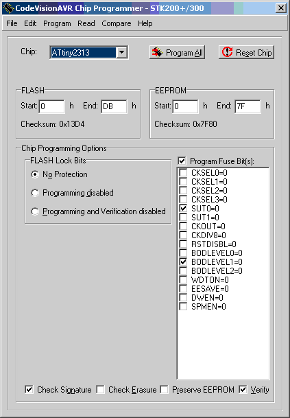
FUSE bits were written off from the MK and left unchanged. I analyzed them, everything is fine there.


Thus, the scheme of the device was not only copied, but also a program was developed on the MC, which in terms of functionality does not differ from the original one. Moreover, the opportunity at the software level is quite flexible (and, most importantly, free) to change the time parameters of the device and use the control pin (No. 1 on the terminal) in various functionals. The program is so simple that you can (even better) write it in assembler, but I am not doing it yet.

Source: https://habr.com/ru/post/414345/


All Articles