In this publication, I will share the experience of creating an IoT device from zero: from the emergence of an idea and its embodiment in hardware to creating firmware for the controller and a web interface to control the created device via the Internet.
Before creating this device, I:
- Almost did not understand the circuitry. Only at the level of principles of work
resistor / transistor ... I had no experience in creating any complex circuits. - Never designed a printed circuit board.
- Never soldered SMD component. The soldering level was at the level of soldering wires and some kind of relay.
- Never wrote such complex programs for the microcontroller. The whole experience was at the level of “light the LED in the Arduino”, and I met the ESP8266 controller for the first time.
- He wrote quite a bit in C ++ for the “big brother”, but this was more than a decade ago and everything was long forgotten.
Of course, experience as a programmer (mainly Microsoft .NET) and system thinking helped me to understand the topic. I think the reader of this publication can also. Useful links and articles on the Internet the sea. Most, in my opinion, interesting, and helping to understand the topic, I cite in the course of the article.
Formulation of the problem
I live in a private house near Minsk, and my own pool, albeit the simplest frame, is an integral part of the set of "benefits" that many people living in a country house receive. In our unstable climate, it turned out that it is uncomfortable to swim in the pool if it is standing outdoors: the water is cooled at night, and the windy daytime does not make bathing comfortable. Last year, with my own hands, I built the Fuller geodesic dome over the pool, set the hill and hung up a bungee - the children are happy.
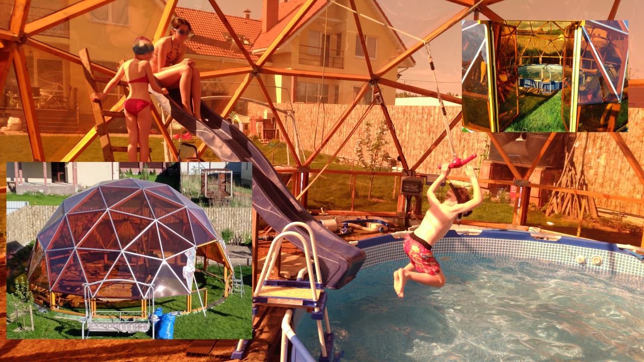
Photos from the construction of the dome on Flickr.
This year I went even further and decided to organize the heating of the pool from the gas boiler,
which serves to heat the house in the winter and to heat the hot water in the summer.
For the summer, the “heating” circuit of the boiler is switched to heating with the help of valves.
the pool. The pool water is heated using a titanium heat exchanger, the primary circuit of which passes the coolant (hot water without impurities) from the heating circuit, and the secondary circuit - water from the pool, pumped by the recirculation pump of the filtration system. Since I use a swimming pool with a chlorinator (a lot of interesting on the topic is painted on the ForumHouse ), water contains a little salt and the heat exchanger needs titanium. You can’t just take and run water directly through the boiler - otherwise, all pipes will be eaten with salt.

Passing through the heat exchanger, the coolant heated by the boiler, with a temperature of about 70-90 ° C, gives off heat to the water from the pool, heating it by a couple of degrees. The coolant itself at the same time cools down by a couple of tens of degrees, and returns to the boiler so as to be again
heated. The ratio of cooling water from the boiler to the pool water depends on many factors: the capacity of the heat exchanger and the rate of water circulation in the primary and secondary circuits.
Pipes supplied from the pool to the heat exchanger are ordinary polyethylene pipes, such as
currently used for the supply of cold water in private homes. Low cost, the ability to withstand decent pressure, no corrosion - these are the main advantages of such pipes. For all, without exception, polyethylene pipes, the operating temperature is limited to 40 degrees Celsius. In principle, for the pool this is more than enough.
However, there is a high probability of an emergency developing in case the pump
water pool recirculation will stop for any reason, and the boiler will continue to heat the heat exchanger: in this case, the water in the secondary circuit of the heat exchanger will quickly rise to the temperature of the primary circuit, which means that the areas of the polyethylene pipes adjacent to the heat exchanger will melt all the space around.
Provision should be made to protect the heat exchanger from overheating.
Fast decision
To solve this problem, a flow sensor operating on the principle of a hall effect was included in the circuit of the pool water recirculation circuit. In addition, temperature sensors located on the secondary circuit
heat exchanger, provide a second echelon of defense, tracking possible overheating.
It is impossible to control overheating by temperature sensors only: the system has a high inertia: after a sudden stop of water in the pool circuit, when
turning off the boiler, the temperature still continues to rise for some time, because the boiler still, by inertia, chases the warmed-up water along the contour, preventing overheating of “me, beloved one”.
Therefore, it is important to react as early as possible: namely, to stop the flow of water in the circuit
the pool.
A flow sensor was used like this . The plastic case and the lack of contact of the sensor with water allows it to be used in salted water.
Temperature sensors, it was decided to use the Dallas DS18B20, they are easy to connect several pieces on one bus 1-Wire at once.

It was decided to hang a pair of sensors on the input and output of both the secondary and primary
contour: only 4 sensors. An additional advantage of this approach is
the ability to monitor system parameters: it is possible to monitor how much the coolant is cooled in the primary circuit and how much the water from the pool in the secondary circuit is heated. And that means - to monitor the optimality of heating and predict the time to turn on the heating.
Installation locations of sensors on the heat exchanger and supply pipes Device parameters
The first prototype of the device was built on the basis of the Arduino Uno, and successfully launched.

But then it turned out that I would like more. Heated 16 cubic meters of water, even just
a few degrees is not a quick matter. And I would like to track the heating parameters straight from work, turn it on / off. But at the same time it would be interesting to take heat graphs, for example, for a day.
Well, since we already get an IoT device, then why don't we control the remote inclusion of the pool chlorinator and the pump for it at the same time?
Terms of Reference
So, it was decided to develop a device - a multifunctional pool controller. He should be able to:
- Control the pool heating through the heat exchanger, turning on / off the gas boiler to heat the water.
- Prevent overheating of the heat exchanger by monitoring the presence of pool water flow in the secondary circuit and the temperature of the secondary circuit.
- Display real-time heat statistics (inlet and outlet temperature for both circuits).
- Record (log) temperature values in flash memory. Display data for
specific period as a graph. - With the help of the relay to be able to turn on / off the pool pumps and the chlorinator.
- Manage all device parameters remotely through the built-in micro-web server.
There was another temptation to screw Blink, MQTT. But from these "frills" in the first stage
It was decided to refuse. And even more, I would not want to endure the possibility of controlling somewhere outside. Built-in web server for my purposes is enough. And security is ensured by the fact that you can enter the home network from the outside world only via VPN.
Hardware
As a controller, it was decided to use a cheap and popular ESP8266. It was perfect for my purposes, except for one thing: matching the signal levels of 5-volt sensors with 3.3 volt controller logic. In principle, the Dallas sensors seem to work on 3 volts, but I have a rather long line from the controller to the sensors, about 7 meters. Therefore, better voltage is higher.
It was determined that it is necessary to have on the "gland":
- ESP8266 controller or its older brother ESP32 (as a DevKit module).
- Matching signal levels for sensors.
- Power regulator 5-volt part of the scheme.
- Relay control module.
- Clock RTC + flash memory for recording logs.
- The simplest 2-line LCD display to display the current values of the sensors and the status of the device and the relay.
- Several physical buttons to control the state of the device without access via the web.
Many components from the list are sold as modules for Arduino and many modules are compatible with 3.3v logic. However, I didn’t want to bundle all this on the breadboard board, because I want to have a neat beautiful device. Yes, and for the money given to the Chinese for the modules, you can completely draw and order your individual printed circuit board, and the wait for her arrival will be compensated by a relatively fast and reliable installation.
Once again, I note that this is my first experience in circuit design and hardware design of such things. I had to study a lot. After all, in the specialty I'm a little away from microcontrollers. But doing everything “on my knees” was not allowed by the spirit of perfectionism living in me.
Schematic diagram
There are a large number of programs on the market that allow you to draw a circuit and a printed circuit board. I, without experience in this area, immediately liked EasyEDA - a free online editor that allows you to beautifully paint a schematic diagram, check that nothing was forgotten and all components have connections, draw a printed circuit board, and then immediately and order its production.
The first difficulty I encountered was that there are quite a few DevKit ESP8266 or ESP32 controller options, some of them differ in pin placement and purpose, and some even in width. It was decided to paint the circuit in such a way that DevKit could be installed in any width and with any pin arrangement, and 2 rows of paired jumper holes should be on each side of it, and subsequently the wiring should be connected to the particular controller.
Space for the controller and 2 rows of paired jumpers: JH1 and JH2 in the diagram:

The location of the pins of the 5v input and the 3.3v output of the power supply of the built-in stabilizer, as well as the GND, seemed to be of the same type for different DevKit, but still I decided to play it safe and also make them jumpers: JP1, JP2, JP3 on the diagram.
Jumpers on the part of connecting them to the components of the circuit, I decided to sign the functions that they are likely to perform.
And this is how it looks with DevKit ESP8266, which I eventually bought and set Here, D1 (GPIO5) and D2 (GPIO4) are responsible for I2C bus, D5 (GPIO14) for 1-Wire, D6 (GPIO12) for receiving pulses from the flow sensor.
Schematic diagram:
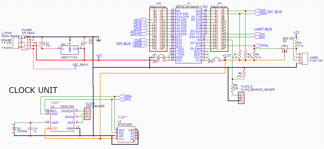
(image is clickable)
Despite the presence on board of the ESP8266 built-in power regulator on 3.3v, we still need to have 5 volts to power the sensors and LCD, and 12 volts to power the relay. It was decided to make the board supply 12 volts, and the input voltage regulator AMS1117-5.0, giving the output the required 5 volts.
To match the signal levels of the 1-Wire bus, I used the BSS138 c field-effect transistor with “suspenders” for voltage on both sides.

Very good about the harmonization of levels is written in the article Harmonization of logical levels of 5V and 3.3V devices .
To match the signal levels of the flow sensor, I simply used a voltage divider across the resistors. The flow sensor is simply an open collector device. Some sensors may already have a built-in pull-up resistor, this should be taken into account:
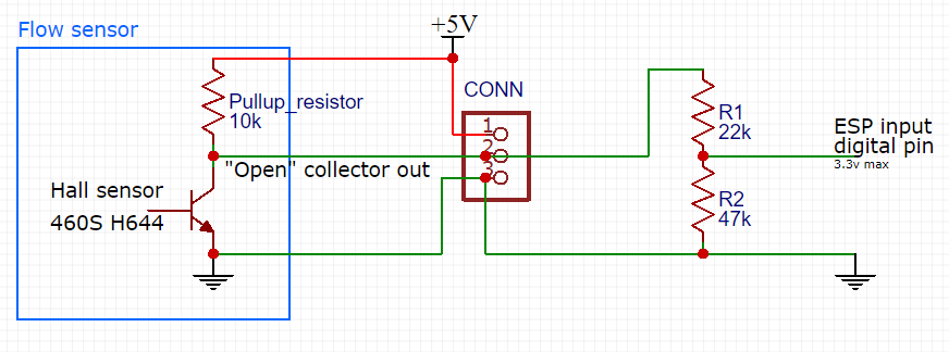
The blue on the diagram is the schematic designation of the flow sensor assembly. To the right of the connector are voltage dividers that I have chosen so as to have a maximum level of 3.3 volts at the output.
On the I2C bus, I hung the DS3231SN real-time clock and the AT24C256C flash memory for storing logs. The flash memory built into the ESP8266 is not suitable because it has a small number of rewrite cycles (10 thousand versus 1 million for AT24Cxxx, according to datasheets).
Relay management is organized on a bunch of PCF8574AT and ULN2803A chips.
The first chip is a microcontroller I2C port extender. The state of the active output or input PCF8574AT is selected by selecting the address on the I2C bus.
The chip has some interesting features, well described in the I2C article PCF8574 port extender .
Directly load (relay) can not control the chip. To do this, use a transistor matrix ULN2803A. There is a feature: the matrix can easily attract its outputs with a load to the ground, which means that if a supply voltage is applied to the second pole of the relay, current flows through the relay coil and the relay contacts close. Unfortunately, with this switch-on we get a side effect: the signal value from the controller is inverted, and all relays “switch over” when the circuit is turned on. I have not yet figured out how to remove this feature.
More details about the chip are described here .
The PCF8574AT port extender can also be used as an input: you can hang hardware buttons on a part of the inputs by reading their values via the I2C bus. In the diagram, pins 4–7 can be used to read the state of the buttons. The main thing is not to forget to programmatically include a built-in tightening of the corresponding legs to the power.
At the same time, I left the wiring on the transistor matrix, in case you suddenly want to connect additional relays. For possible connections, I connected all the leads to the connectors (more precisely, to the holes for them, where wires can be soldered or a standard 2.54 mm DIP connector is soldered).
Pin INT port extender can be used to quickly respond to a button click. It can be connected to a free port on the controller and set an interrupt trigger by changing the state of this pin.
The two-line LCD display is also controlled via the PCF8574AT expander. The main point: the display is powered from 5 volts, while the display itself is controlled by 3-volt logic. By the way, standard Arduino-adapters for I2C are not designed for dual voltage. The idea of such a connection, I found somewhere on the Internet, unfortunately, I lost the link, so I do not cite the source.
Printed circuit board
When designing the board, it turned out that the usual parts with legs take up too much space, and many DIP chips are not easy to find. After reading on the Internet that SMD installation is not so complicated, and with proper skill even less laborious, I decided to design a board for SMD parts. And no mistake. It turned out a compact, beautiful board, where I easily placed everything I need. SMD parts, with a good soldering iron, flux and solder, it turned out really very easy to install.
On the board, I added a few square fields of holes for the layout, if you suddenly want to add something else.
The printed circuit board I made was 97x97 mm. It easily fits into a standard electrical chopping box. In addition, boards with dimensions less than 100x100 are cheap to manufacture. The production of a minimum batch of 5 boards on the basis of the developed layout cost 5 USD, and another 9 USD was worth their delivery to Belarus.
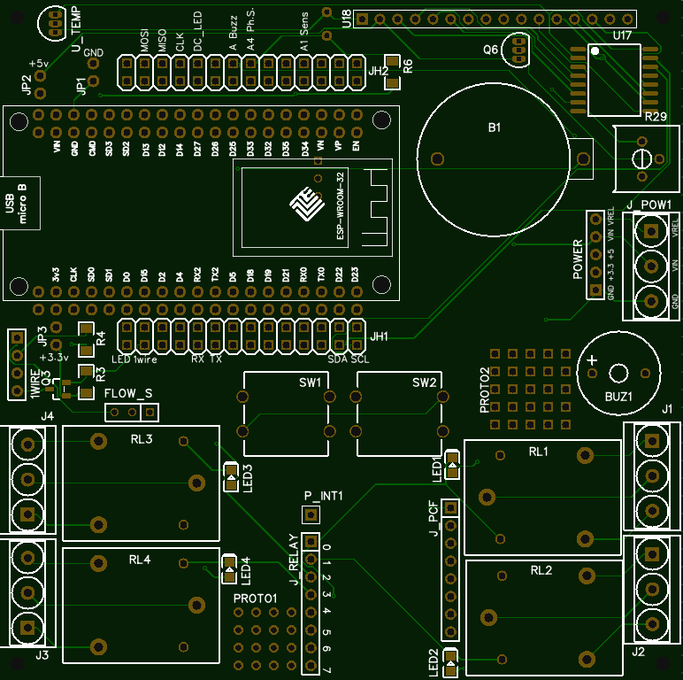
The project fee is on the EasyEDA website and is available to everyone.
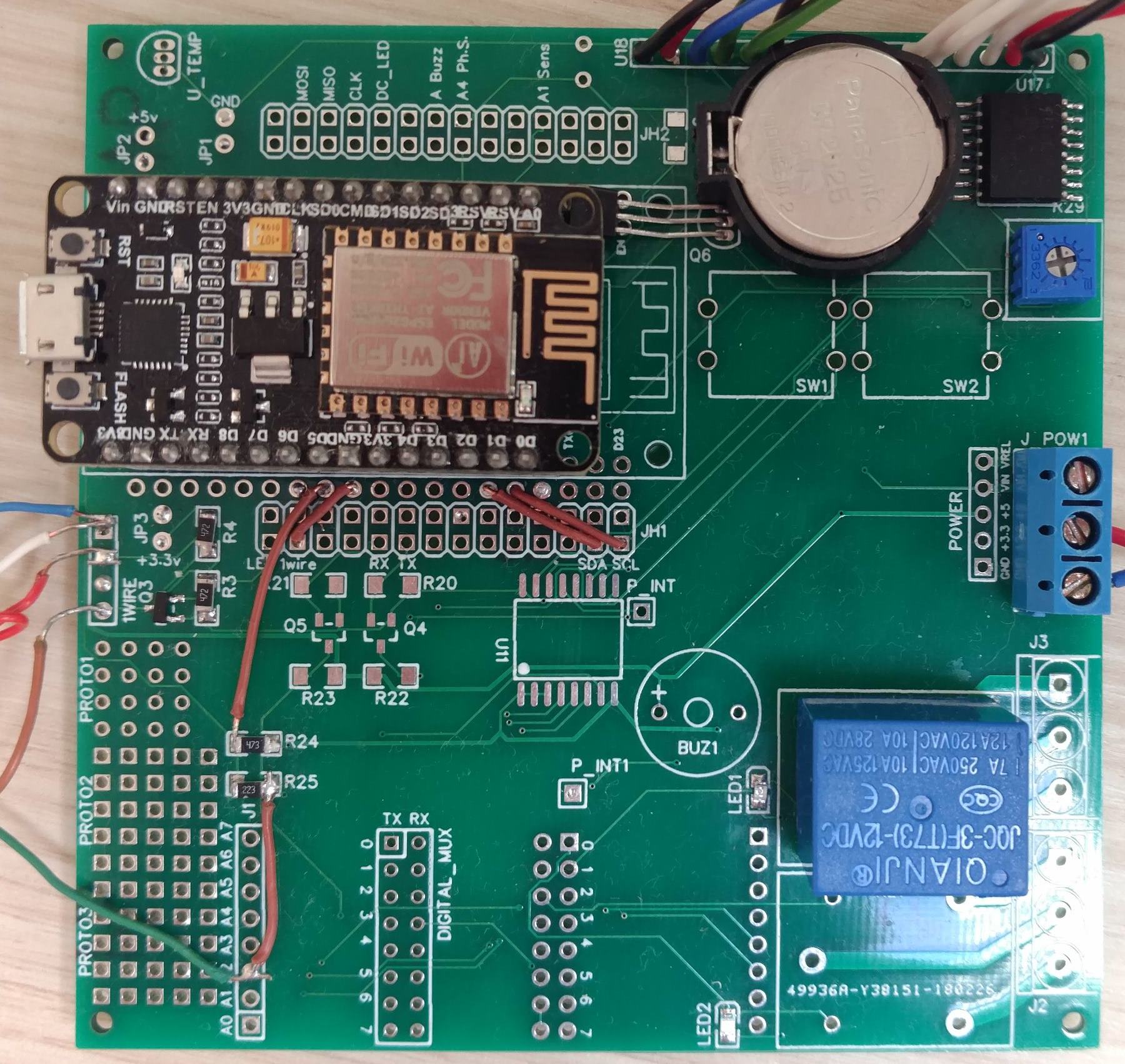
I note that the photo of the controller below features the first sample of the board, for which I “fiddled” with a lot more that was unnecessary and unnecessary (in the hope of using this minimum batch of 5 boards and in other projects). Here and on EasyEDA, I laid out an option that was “cleaned” from all these unnecessary features.
Photos of both sides of the boardFront side:
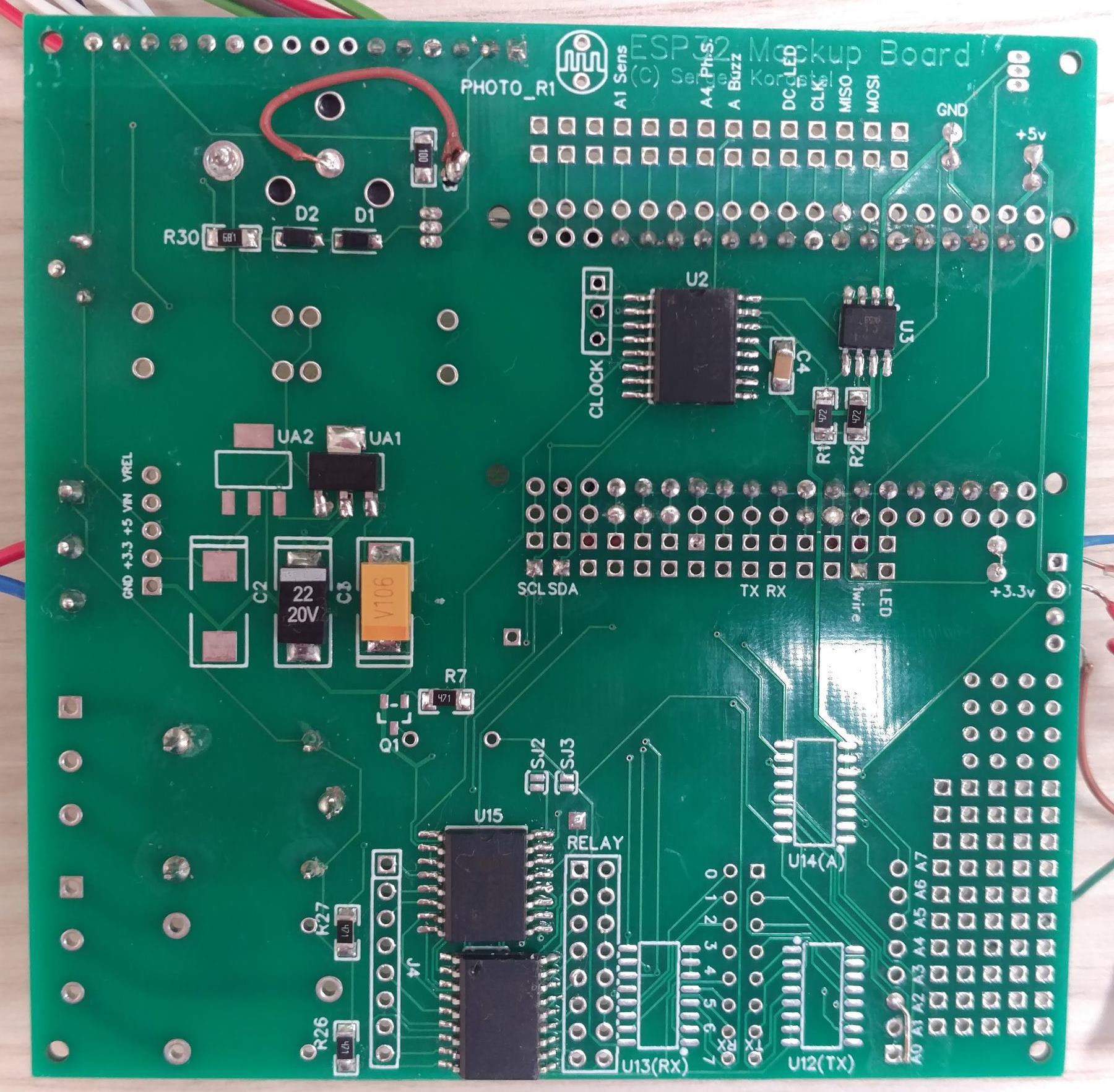
Backside:
Software part
For programming the microcontroller, given the backlog in the form of a prototype for the Arduino Uno, it was decided to use the Arduino environment with the
ESP8266 Arduino Core installed. Yes, you can use
Lua on the ESP8266, but they say there are suspensions. I, given the critically important function performed, would not like that at all.
The Arduino environment itself seems a bit obsolete to me, but fortunately, there is an
extension for Visual Studio from Visual Micro. The environment allows you to use IntelliSence hints on the code, quickly move to the function declarations, refactor the code: in general, everything that the environment allows itself for "adult" computers. The paid version of Visual Micro also makes it easy to debug the code, but I was content with the free option.
Project structure
The project consists of the following files:
Project structure in Visual Studio | File | Purpose |
|---|
WaterpoolManager.ino
| Declaring basic variables and constants. Initialization. The main loop.
|
HeaterMainLogic.ino
| The main control logic of the boiler relay (temperature) and auxiliary relays.
|
Sensors.ino
| Reading sensor data
|
Settings.ino
| Device settings, saving them to the controller's flash memory
|
LCD.ino
| Information display on LCD
|
ClockTimer.ino
| Reading RTC clocks, or clock simulation
|
Relays.ino
| Relay on / off control
|
ButtonLogic.ino
| Logic of reaction to hardware button states
|
ReadButtonStates.ino
| Reading hardware button states
|
EEPROM_Logging.ino
| Logging sensor data in EEPROM
|
WebServer.ino
| Embedded web server for device management and status display
|
Webpages
| Web server pages are stored in this folder.
|
index.h
| The main page displays the status of the device. The current state is being read by calling ajax. Refresh every 5 seconds.
|
loggraph.h
| Displays a log of sensor data and relay states as a graph. The jqPlot library is used - all building takes place on the client side. The request to the controller goes only to the binary file - copies of data from the EEPROM.
|
logtable.h
| too, but as a table
|
settings.h
| Controlling device settings: setting limits for temperature, water flow, frequency of data logging
|
time.h
| Set the current time
|
| Libraries
|
EepromLogger.cpp
| Library of writing logs in flash
|
EepromLogger.h
|
crc8.cpp
| Counting the 8-bit CRC for the library
|
crc8.h
|
TimeSpan.cpp
| Structure for managing time spans
|
TimeSpan.h
|
Sensor survey
When the device starts, it searches for temperature sensors on the OneWire bus and enters their addresses into the tempSensAddr array. Sensors are entered in the order of their response on the bus and the order does not change in the future. The index of the last sensor in the array is remembered (the device can work with 4 or fewer sensors):
while (ds.search(tempSensAddr[lastSensorIndex]) && lastSensorIndex < 4) { Serial.print("ROM ="); for (byte i = 0; i < 8; i++) { Serial.print(' '); Serial.print(tempSensAddr[lastSensorIndex][i], HEX); } if (OneWire::crc8(tempSensAddr[lastSensorIndex], 7) != tempSensAddr[lastSensorIndex][7]) { Serial.print(" CRC is not valid!"); } else lastSensorIndex++; Serial.println(); } ds.reset_search(); lastSensorIndex--; Serial.print("\r\nTemperature sensor count: "); Serial.print(lastSensorIndex + 1, DEC); , (). Serial LCD : // Read sensor values and print temperatures ds.reset(); ds.write(0xCC, TEMP_SENSOR_POWER_MODE); // Request all sensors at the one time ds.write(0x44, TEMP_SENSOR_POWER_MODE); // Acquire temperatures delay(1000); // Delay is required by temp. sensors char tempString[10]; for (byte addr = 0; addr <= lastSensorIndex; addr++) { ds.reset(); ds.select(tempSensAddr[addr]); ds.write(0xBE, TEMP_SENSOR_POWER_MODE); // Read Scratchpad tempData[addr] = ds.read() | (ds.read() << 8); // Read first 2 bytes which carry temperature data int tempInCelsius = (tempData[addr] + 8) >> 4; // In celsius, with math rounding Serial.print(tempInCelsius, DEC); // Print temperature Serial.println(" C"); }
According to the datasheet, the sensors require at least 750 ms delay between requesting a temperature value and receiving a response from the sensor. Therefore, the code introduced a delay with a small margin.
However, this delay, when the entire device simply waits for an answer, is acceptable at the start, but it is absolutely inappropriate to wait each time with regular polling of sensors. Therefore, the following tricky code was written, called every 50 ms by timer:
#define TEMP_MEASURE_PERIOD 20 // Time of measuring, * TEMP_TIMER_PERIODICITY ms #define TEMP_TIMER_PERIODICITY 50 // Periodicity of timer calling, ms timer.attach_ms(TEMP_TIMER_PERIODICITY, tempReadTimer); int tempMeasureCycleCount = 0; void tempReadTimer() // Called many times in second, perform only one small operation per call { tempMeasureCycleCount++; if (tempMeasureCycleCount >= TEMP_MEASURE_PERIOD) { tempMeasureCycleCount = 0; // Start cycle again } if (tempMeasureCycleCount == 0) { ds.reset(); ds.write(0xCC, TEMP_SENSOR_POWER_MODE); // Request all sensors at the one time ds.write(0x44, TEMP_SENSOR_POWER_MODE); // Acquire temperatures } // Between phases above and below should be > 750 ms int addr = TEMP_MEASURE_PERIOD - tempMeasureCycleCount - 1; if (addr >= 0 && addr <= lastSensorIndex) { ds.reset(); ds.select(tempSensAddr[addr]); ds.write(0xBE, TEMP_SENSOR_POWER_MODE); // Read Scratchpad tempData[addr] = ds.read() | (ds.read() << 8); // Read first 2 bytes which carry temperature data } }
At the beginning of each cycle, tempMeasureCycleCount, a request is made to the sensors to read their values. After about 50 such cycles pass (and in total it is 50 * 20 = 1000 ms = 1 sec), the value of each sensor is read, one at a time. All work is broken into pieces so that the code that runs in the timer interrupt does not take much time from the controller.
The value of the flow sensor is calculated as follows. According to the interruption on the pin on which the sensor hangs, we increase the value of the tick counter that came from the flow sensor:
pinMode(FLOW_SENSOR_PIN, INPUT); attachInterrupt(digitalPinToInterrupt(FLOW_SENSOR_PIN), flow, RISING); // Setup Interrupt volatile int flow_frequency; // Flow sensor pulses int flowMeasureCycleCount = 0; void flow() // Flow sensor interrupt function { flow_frequency++; }
In the same timer where temperature sensors are polled, once a second we take this value of ticks and translate into liters using the constant FLOW_SENSOR_CONST, the value of which can be found in the sensor characteristics:
flowMeasureCycleCount++; if (flowMeasureCycleCount >= 1000 / TEMP_TIMER_PERIODICITY) { flowMeasureCycleCount = 0; litersInMinute = (flow_frequency / FLOW_SENSOR_CONST); // Pulse frequency (Hz) = FLOW_SENSOR_CONST*Q, Q is flow rate in L/min. flow_frequency = 0; // Reset Counter }
Logging data from sensors and instrument status
In developing the logging mechanism, the fact that the device can be suddenly turned off, i.e. at almost any moment. When you stop recording, we should be able to restore everything recorded until the very last moment. At the same time, we cannot constantly overwrite one and the same area of flash memory (for example, a certain title in a certain place, remembering the address where the last recording took place), in order to avoid accelerated “wiping” the flash drive in this place.
After some "kumakan" the following model of the record was invented and implemented:

Each record is a record containing information about the current value of the water flow, the temperature of the sensors, as well as the device status encoded in the byte (the individual bits indicate whether the relay is on or not, heating is allowed or not):
struct LogEvent { unsigned char litersInMinute = 0; unsigned char tempCelsius[4]{ 0, 0, 0, 0 }; unsigned char deviceStatus = 0; }
After each entry, there is a CRC checksum byte indicating whether the entry was recorded correctly and, in general, whether at least something was recorded in this memory location.
Since it would be too expensive for the volume to record data about the current time ( timestamp ) for each record, the data are organized in large blocks, with N records each. Timestamp for each block is recorded only once, for the rest - is calculated based on information about the frequency of logging.
unsigned int logRecordsInBlock = 60 * 60 / loggingPeriodSeconds; // 1 block for hour unsigned int block_size = sizeof(Block_Header) + logRecordsInBlock * (record_size + crcSize); unsigned int block_count = total_storage_size / block_size;
For example, if the frequency of logging is every 30 seconds, we will have 120 entries in the block, and the block size will be about 840 bytes. All we have to fit 39 blocks in the memory of a flash drive the size of 32 kilobytes. With such an organization, it turns out that each block starts at a strictly defined address in memory, and running through all the blocks is not a problem.
Accordingly, in the event of a sudden break in the record when the device is turned off, we will have an unfinished block (that is, in which some of the records are missing). When the device is turned on, the algorithm searches for the last valid block header (timestamp + crc). And continues to record, starting with the next block. Recording is performed cyclically: the most recent block overwrites the data of the oldest block.
When reading is a sequential reading of all blocks. Nonvalid blocks (those that fail the CRC check for the timestamp) are ignored entirely. Entries in each block are read until the first invalid entry is met (that is, the one on which the record was broken last time, if the block was not recorded entirely). The rest are ignored.
For each record, the current time for it is calculated, based on the timestamp of the block and the sequence number of the record in the block.
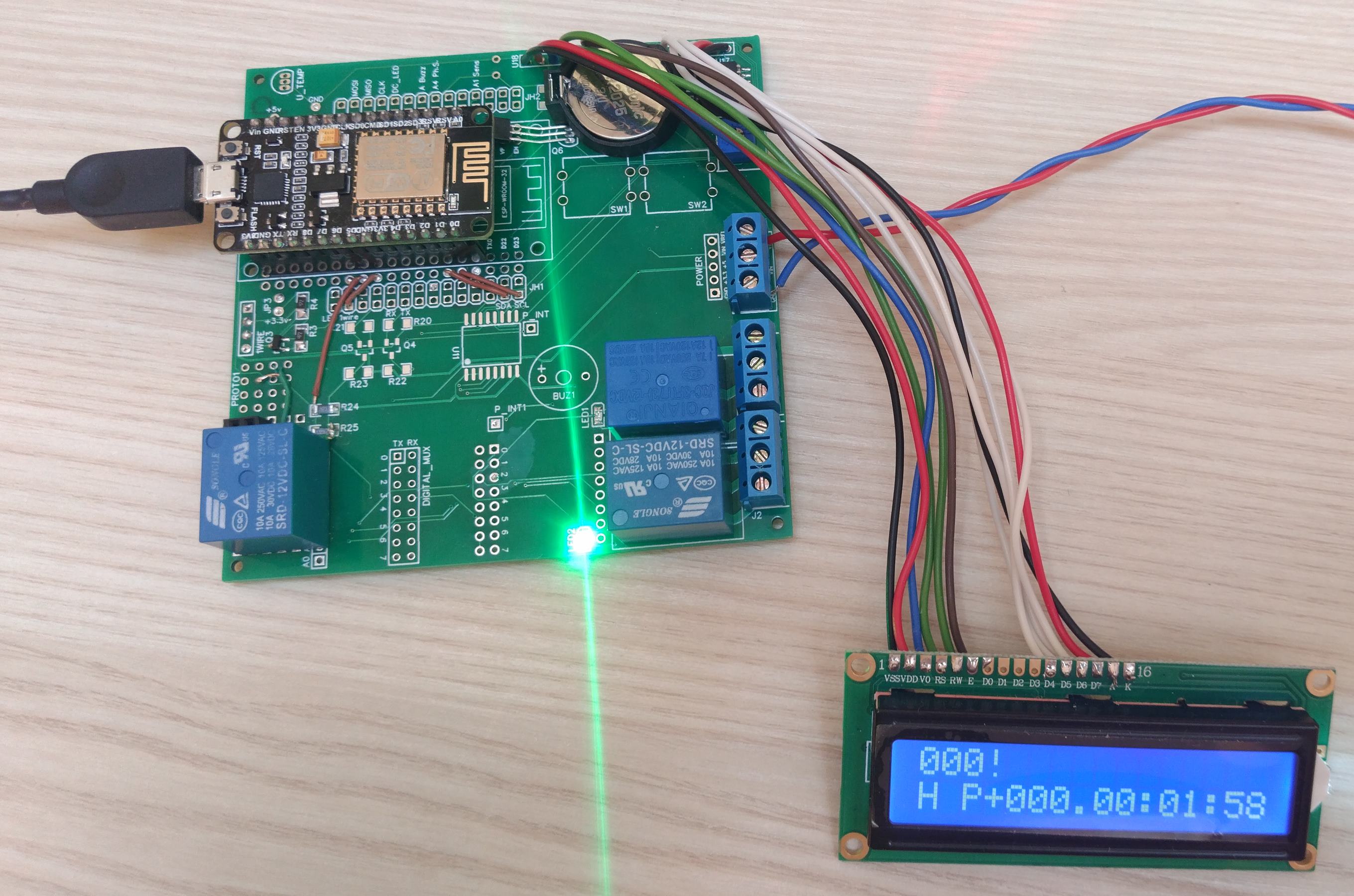
LCD
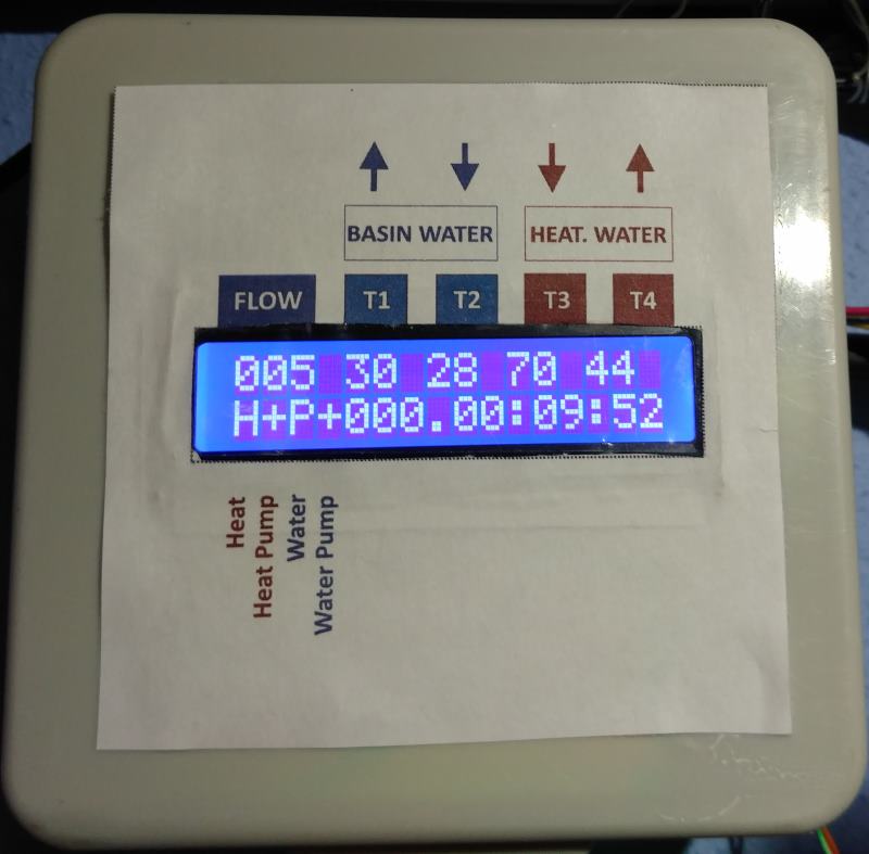
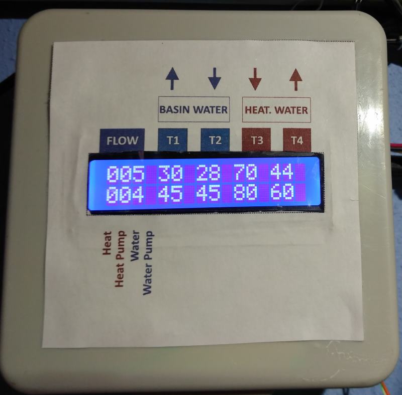
The device uses a QC1602A display capable of displaying 2 lines of 16 characters each. The first line displays current information about the current values of the sensors: flow and temperatures. If the specified limit is exceeded, an exclamation mark appears near the value. The second line shows the state of the heating relay and the pump, as well as the time elapsed since the heating was turned on or off. Every 5 seconds the display in the second line briefly shows the current limits. Photographs of the display in various modes are given at the end of the publication.
Charts
When requesting via the embedded web server, the logging data is read in binary form using JavaScript:
var xhttp = new XMLHttpRequest(); xhttp.open("GET", "logs.bin", true); xhttp.responseType = "arraybuffer"; xhttp.onprogress = updateProgress; xhttp.onload = function (oEvent) { var arrayBuffer = xhttp.response; if (arrayBuffer) { var byteArray = new Uint8Array(arrayBuffer); … }}; xhttp.send(null);
Reading them in some popular non-binary format, for example ajax, would be an unaffordable luxury for the controller, primarily because of the large volume that the built-in http server should return.
For the same reason, the jqPlot JavaScript library is used for plotting , and the JS library files themselves are loaded from popular CDNs .
Example of the device operation schedule:
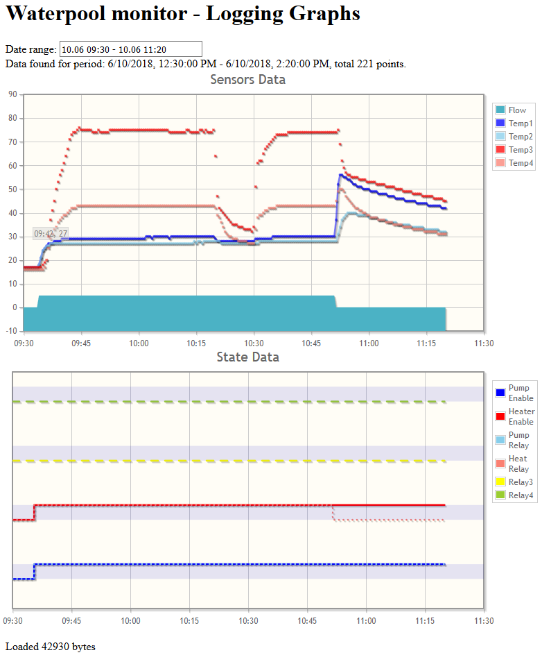
It can be clearly seen that at about 9:35 the device was turned on for heating, the boiler gradually began to heat the heating circuit (sensors T3, T4), after which the temperature of the pool circuit began to rise (sensors T1, T2). Somewhere around 10:20 the boiler switched to heating the hot water in the house, the temperature of the heating circuit dropped. Then after another 10 minutes, the boiler returned to heating the pool water. At 10:50 an accident occurred: suddenly the water circulation pump in the pool was turned off. The water flow plummeted to zero, the heating relay turned off (red dotted line on the 2nd chart), preventing overheating. But the device still remains in the state of heating (red line on the 2nd chart). Those. if the pump were turned on again and the temperatures were normal, the device would return to heat. I note that after the emergency shutdown of the pump, the temperature in the pool water circuit (T1, T2) began to rise sharply due to overheating of the heat exchanger. And if not for the abrupt shutdown of the boiler, there would be trouble.
Embedded web server
To communicate with the outside world, the standard class ESP8266WebServer is used . When the device starts, it is initialized as an access point with the default password specified in #define AP_PASS. A web page automatically opens to select an available wi-fi network and enter a password. After entering the password, the device reboots and connects to the specified access point.
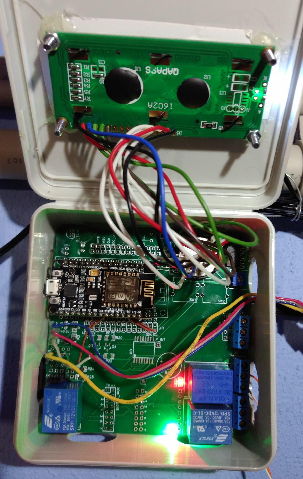
Ready device
The finished device was placed in a standard cutting box for wiring. There was a hole in it for the LCD, and holes for the connectors.
Photos of the facade of the device in different modesWith the display of the elapsed time:
With the display of limits:
Conclusion
In conclusion, I want to say that while developing such a device, I got an excellent experience with circuit design, printed circuit board development, SMD assembly skills, architecture and programming of microcontrollers, I remembered almost already forgotten C ++ and careful memory handling and other limited controller resources. Also knowledge of HTML5, JavaScript, skills of debugging of scripts in the browser were useful to some extent.
These skills and the pleasure obtained by developing the device are the main benefits obtained. And the source codes of the device, schematic diagram, printed circuit boards - please use, modify. All source codes of the project lie on GitHab. Hardware in a public project on EasyEDA. Datashity to the chips used in the project, I collected on a network drive .