Acceleration: the old woman claims that the "Moskvich" low-quality gearbox
© M. Zhvanetsky"Forty-first"
In 1985, a new Moskvich-2141 car appeared in the USSR.
It was planned that this car of the third group of small class will occupy a consumer niche between the mass V8-VAZ-2108 of the second group of the small class and the prestigious Volga GAZ-24-10 of the middle class.
Quite a big, high-speed, comfortable (by Soviet standards) car with some elements of chic (VHF radio in the box!), The dream of a Soviet person.
In addition to ... a number of reasons beyond the scope of this article, this was hampered by the lack of a sufficiently powerful engine, as well as an automatic transmission.
And if the problem with the engine was supposed to be solved over time by switching from UZAM-331.10 and VAZ-2106 to a new family of engines AZLK-21414, under which the construction of a new plant began, then everything was more sad with an automatic transmission. Strictly speaking, not a single massive Soviet car could boast an automatic transmission, including the ultimate dream of the Soviet nomenclature of the 24th Volga.
However, some ideas nevertheless were, and those who are interested in the history of Soviet automobile technology are welcome under the cat.
The idea to make an automatic transmission on the basis of a variator for “Moskvich” arose even before the official birth of the 41st “Moskvich”, first in the form of a graduation project, which was made by the author of this article (then still a MAMI student) in NAMI, and then in UCER AZLK the author’s initiative (and mostly with his own hands), first “in his spare time,” and later also in various “plans for the creation of promising technology” *.
- It should be noted that, in addition to the continuously variable transmission developed for production vehicles of the Moskvich-2141 family, the AZLK also developed another interesting continuously variable transmission based on the torus variator as part of the project Car of the Year 2000, but “this is a completely different story, requiring a separate large conversation.
Since this transmission was supposed to be installed on a car that is in current production, the design changes of which were practically unacceptable, it was required that its installation did not entail any changes in the bodywork (up to the attachment points), as well as changes in other components and assemblies (for example exhaust system, passing near the transmission, steering rack, located slightly above, etc.). This imposed severe restrictions on the dimensions of the structure.
For example, in this photo on the variator case one can see a “liska” (circled in red), which was made in order to diverge from the body tunnel with the necessary clearance.Variable speed drive
The basis of the continuously variable transmission was taken “V-chain” variator with smooth pulleys of the German company
PIV , which was widely used in the drives of ship generators, paper machines and other industrial equipment, requiring a smooth change in the gear ratio.
On the basis of the same variator, he designed his continuously variable transmission Volkswagen, and a little later
LuK , which absorbed the PIV, created the
Multitronic continuously variable transmission for AUDI.
A few words about why the PIV variator was chosen, and not the more popular
Transmatic at that time. Other things being equal, the “belt” (more precisely, the chain) of the PIV variator has a greater bearing capacity than the Transmatic metal belt, and as noted above, the dimensions of the continuously variable transmission were subject to very strict limitations. And in general at that time Transmatic was used only on minicars with an engine with a torque of up to 80-100 Nm, and in this case it was assumed that a continuously variable transmission would work with the new AZLK-21414 engine family with a torque of up to 160-180 Nm.
Another, no less important reason was that the production of a continuously variable transmission was planned to be mastered at the existing machine-building plants, and the Transmatic metal belt was too specific, requiring special production arrangements.
At the same time, the PIV chain-strap is structurally similar to a conventional gear chain that is well developed in production and is widely used in industry. Differences only in axes with a special surface of the ends, working on a smooth conical surface of the pulleys. In this case, the axles are made of bearing steel SHKh15, and from the point of view of manufacturing technology are very similar to the details of rolling bearings.
Thus, it was quite possible to master the production of the PIV type chain at one of the USSR bearing plants.
Despite the fact that the prototypes of the continuously variable transmission were a piece product, the design was immediately designed for mass production. Therefore, all documentation was made “in permits” so that the assembly could be carried out without fitting the parts. Carter's prototypes, though cast into the ground on wooden models, were designed for die-casting. The same can be said about other details. So even though it was a prototype, but made almost under the conditions of mass production. This distinguishes it from the majority of home-made, collected "using a file."
Most of the parts were manufactured in the Experimental Department of the UKER AZLK, as well as in other production facilities of the automobile plant, a significant part of the machining was carried out “according to conversion” at
the Almaz Scientific and Production
AssociationStepless transmission design
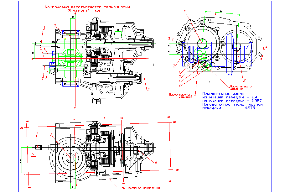
On the layout diagram, you can see that the variator of the continuously variable transmission has a center distance between the driving and driven pulleys of 145 mm, the maximum and minimum gear ratios of 2.4 and 0.357 (1 / 2.8), respectively, ie the gear ratio range is 6.7 (gear ratios are slightly asymmetric , to reduce the load on the circuit in "low gear"). The relatively small maximum gear ratio required a fairly large gear ratio of the main gear of 4.875, fortunately the hypoid gear allows it.
The pulleys are pressed and the variator gear ratio is changed using hydraulic cylinders located in the pulleys.
Since, unlike gearing, the direction of rotation of the drive and driven shafts of the variator coincide, to ensure the required direction of rotation of the wheels of the car, the main gear was turned upside down (the drive gear is located on the other side of the driven gear). In addition to the desired direction of rotation, this enabled the leading and driven shafts of the variator to be moved apart by the required distance.
As a result, if we compare the design of this continuously variable transmission, for example with the “related” design of Multitronic, it is much simpler and more compact. * Backing is obtained with the help of a planetary gear shifted with the help of “wet” multi-disc clutches. They also provide the starting of the car, so that the torque converter in this case is missing. In general, the design of the clutches and reverse resembles the Transmatic scheme, but there are some differences related to the layout features, the design of the variator and the hydraulic control system of the variator and the clutches. *
- A small "lyrical digression."
If we compare the design of this continuously variable transmission with Multitronic, then the designer's trained eye will be able to notice the coincidence of some technical solutions. In this case, "all matches are random." The fact is that the first open publications of the Multitonic design appeared only in the late 90s, i.e. about 10 years after the stepless transmission of the Moskvich was designed. Of course Multitronic was designed before, but the documentation was naturally closed. Apparently simply the need to adapt the bulky design of the industrial variator PIV to a compact automobile transmission forced the designers to move in the same direction.
- But by the design of the Transmatic, there was already some information available, so there are some borrowings, of course, taking into account the peculiarities associated with differences in the design of the Transmatic metal belt and the PIV chain, the longitudinal position of the engine and the features of the hydraulic control system of the continuously variable transmission .
As a result, the mass of the stepless transmission "Moskvich" was only 50 kilograms (and this despite the fact that crankcases cast into the ground are somewhat heavier than die-casting during mass production), which is only 8 kilograms heavier than the usual mechanical gearbox "Moskvich".
Some more photos.The design work on continuously variable transmissions officially began in 1985, and in 1987 they were significantly accelerated due to the meeting at the International Exhibition in Sokolniki with representatives of PIV who showed interest in this work, which resulted in the signing in early 1988 of the “Protocol on intentions. "
In 1988, the manufacture of prototype parts began. According to the plan, the work was to be completed by 1992, but at this stage the work was extremely slow, almost stopped several times, therefore the prototype was finally assembled only in 1995. To this we will return a little lower.
Transmission control system
A purely hydraulic system with hydraulic “logic”, pitot tubes, etc. was originally assumed as a control system.
But even such a “simplest” control system was uncharacteristic for automobile production at that time, and problems arose with this. However, in the late 80s, on the basis of “Perestroika” on the basis of defense enterprises, many cooperatives and small enterprises emerged, including research and production, which they gladly took on similar work.
In this case, a small enterprise formed on the basis of CIAM took up the project.
An electro-hydraulic system was proposed, with electronic logic, for which it was possible to use serial valves and electronic components used for the power supply and control system of aircraft engines.
The control system was a separate plate, installed in a window at the bottom of the transmission.
The photo shows a place to install the control plate, with channels for controlling the power hydraulics of the variator and the clutches.
The hydraulic part of the control system was powered by a gear pump driven by the engine. An oil circulation system with a semi-dry crankcase was used; a second pump (low pressure) was used for this, pumping oil from the variator crankcase to the crankcase through coarse and fine filters.
Work began in 1988, and by 1992, a prototype had been manufactured at a small-scale plant at an aircraft factory - a subsidiary of CIAM.
Unfortunately, by this time, the transmission sample had not yet been made, so the “wedding” of the control system with the transmission was postponed all the time. Eventually, the small enterprise fell apart, and the prototype of the management system was lost.
Control algorithm
The control system must control the transmission in accordance with the algorithm embedded in it.
One of the main tasks of the automobile transmission is to ensure that the engine operates in the optimum mode for it in any driving conditions by selecting the optimal transmission (in the case of a stepped transmission) or a stepless change in the gear ratio (in the case of the variator).
As a result, the engine at any load should work with the minimum fuel consumption for a given load. *
- Of course, in addition to the specific consumption, other parameters should be taken into account, for example, toxicity, engine wear, noise, acceleration, etc.
This can be visualized on the multi-parameter characteristic of the engine.
It shows the rotational speed of the engine crankshaft on the abscissa axis, and its torque on the ordinate axis *, in addition, hyperbolas of constant power are displayed, and the specific fuel consumption per unit of power (grams / kWh) from the minimum (green) to maximum (red).
- In this case, the relative multi-parameter characteristic is taken, on which the engine speed and torque are displayed relative to their maximum values.
It can be seen that the minimum specific consumption is in the zone from about 50% to 80% of the maximum torque in a fairly wide range of power and engine speed.
It can be noted that even at low engine power, it is desirable that its torque is quite large and the rpm is minimal. As the power increases, the engine speed should also increase, and the optimum torque changes very little. Well, at maximum power there is nothing to choose, there is no need for economy, therefore both the load and the speed are maximum.
In the case of a manual gearbox, the driver himself chooses the right gear by adjusting the load with the gas pedal. For example, with intensive acceleration or movement on the rise or off-road, it may be the second gear, and with a quiet movement with the same speed, the fifth gear can be selected.
In the case of an automatic gearbox, the driver sets the mode of operation with the gas pedal, and the box itself selects the desired gear.
Well, in the case of the variator, the gear ratio changes steplessly, allowing the engine to operate at the optimum mode for a given load depending on the position of the gas pedal.
At first glance, it may seem that the control algorithm of a continuously variable transmission is simpler than a stepped automatic transmission, but this is not entirely true.
Those who drove a car of the 1980s with a CVT (for example, Ford Fiesta or Fiat Uno) may have noticed that after moving obstacles (pothole, bump or curb), the engine “howls” for some time (revolutions fluctuate noticeably). The fact is that an obstacle causes a sharp increase in load, because of which the control system causes the variator to increase the gear ratio, then the load decreases, the gear ratio of the variator also decreases, and vibrations result.
Another unpleasant feature of these cars was the feeling of a “failed clutch” when the gas pedal was depressed sharply, for example, when overtaking. The control system receives a signal about the need for a significant increase in engine speed, and is trying to quickly increase the gear ratio of the variator for its acceleration. As a result of such a rapid acceleration of the engine, all its torque goes to the promotion of its own flywheel (approximately the same as when you press the gas pedal sharply on the neutral point). Of course, in half a second-second, the engine will reach the desired mode, and the car will begin to accelerate intensively, but during this time the driver will have time to get negative emotions.
If you just “blunt” the control system, slow down its reaction, then the car will start to react too “thoughtfully” to the smooth operation with the gas pedal, which is also undesirable.
In principle, these troubles can be avoided if the variator control algorithm reacts not only to the rotational speed of the crankshaft, but also to its first, and preferably second derivatives (acceleration of the rotational speed and acceleration of its acceleration).
In this case, the variator and the engine will not react so nervously to sudden changes in load and intensive work with the gas pedal, and at the same time it is sufficiently “sensitive” to track small fluctuations in load and the slightest movements of the gas pedal.
Of course, with the current digital control systems, this is an easily solvable task, therefore, on modern cars with variators, the disadvantages noted above are almost eradicated.
However, in the late 1980s, this was very difficult to accomplish in transmissions with hydraulic and even more advanced electronic logic.
The transmission in question was used at the end of the 50s, proposed by Dr. Sc. V.A. Petrov original control algorithm, devoid of this disadvantage.
At the same time, not the engine speed was used as the “reference signal” for controlling the variator gear ratio, but its torque measured directly after the flywheel (in this case it is an important qualification!).
Of course for this it was necessary to have a torque sensor, but in this case it was originally laid to regulate the pressure in the hydraulic cylinders of the pulleys depending on the same torque.
The torque measurement was carried out on the twist angle of a sufficiently long primary transmission shaft (see the diagram at the beginning of the article).
For this, two Hall sensors were used on the gear rims near the front and rear ends of the input shaft, from the phase difference on which the torque could be calculated. Well, one of these Hall sensors served to measure the engine speed.
The copyright certificate for the invention was issued for this variator control algorithm.
In addition, other technical solutions also received several Author certificates and Patents for inventions.
Epilogue (epitaph)
Unfortunately, the time of manufacture of the prototype of the stepless transmission almost coincided with the coming to power on AZLK of the general director Ruben Astaryan, at which the agony of the plant began. In such circumstances, it was not possible to conduct normal tests, not to mention the mastering of production. Well, after a few years and the car itself finally became bankrupt.
However, "this is a completely different story", sad and very sad ...
PS: Photos in higher resolution can be viewed in
my photo album
PpsI tried to write this article a long time ago, but for some subjective reasons, it could not be obtained. In the end, I realized that if I did not publish it now, I would never write. I apologize for some confusion, I usually write easier. If this topic is of interest, it will be possible to continue.