It is a translation. Article published May 27, 2018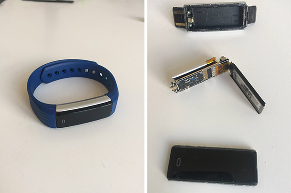 Fitness tracker before and after disassembly
When I came to the current company, on the first day I was kindly given a set of gifts. Among them was this bracelet with a fitness tracker. Regardless of your love of exercise, this is an incredibly cool gadget from a purely technical point of view:
- really small form factor (about 15 × 40 mm);
- Bluetooth low energy (BLE);
- OLED display (96 × 32 pixels);
- battery;
- USB charging;
- accelerometer;
- vibration motor;
- The price is about $ 10 (!).
Outside on the back panel, the only identifier is the “FCC ID: 2AHFTID115” label. If you google it, it seems to correspond to the device
ID115 and you can even find a
few photos of its insides. Looking back, in
one of these photos , if you try hard, you can see the name of the largest integrated circuit (IC): N51822. This suggests that there may be a
nRF51822 microcontroller (MCU)
from Nordic , a 32-bit ARM M0 processor with integrated BLE support, which is theoretically easy enough to program into other things that a bracelet should do.
Before disassembling the gadget, I went a little googling and found out that
some similar bracelets had the same chip installed, and people were successfully programming it.
Open the case was not so easy. The black plastic cover is glued to the gray back. I tried a hair dryer to soften the glue, and patiently cut it with a small knife, trying not to damage the plastic too much. After the autopsy, I made sure that there really is nRF51822. Later, I bought a nearly identical MCU bracelet from Texas Instrument. Keep in mind that there are options.
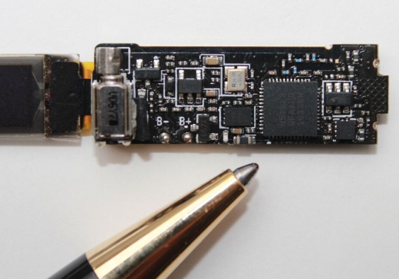
 nRF51822 and ballpoint pen for scale
Search for communication
The
documentation states that the chip can be programmed / debugged using the ARM
Serial Wire Debug (SWD) two-prong interface. If we want to establish a communication channel with a chip, then this means two things:
- We will need a SWD programmer (for example, Segger J-Link ).
- We will need access to two SWD pins on the microcontroller, namely SWDIO (data) and SWDCLK (clock pulses).
Fortunately, the board has several available pads. Although their existence is clearly explained by the need to debug, test and verify, I prefer to think that some cool engineer left them there as small gifts for people like us. Not all of them are properly labeled, so I propose such codes:
 Front and back sides of the PCB. Ballpoint pen for scale and semi-arbitrary names for open contact pads
Using the same cheap
USB microscope, I took several pictures of the front and back sides of the board and tried to track the tracks from the microcontroller to the contact pads.

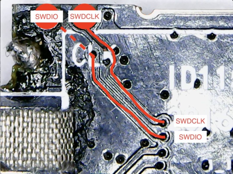 Tracks to the SWDIO and SWDCLK contacts on the front and rear sides of the board
Please note that this is a multi-layer PCB with through holes, so you should check the tracks on both sides of the board. These photos can track the tracks from the SWDIO and SWDCLK pins on the chip to the IO and CLK pads. So we make sure that the CLK mark on the board corresponds to the SWDCLK on the MCU, and the unlabeled contact is the SWDIO pin. Now we can prepare our first mapping table:
| NRF51822 output | Playground | Description |
|---|
| SWDIO | Io | SWD programming data output |
| SWDCLK | CLK | Clock output for SWD programming |
Post mortem surgery
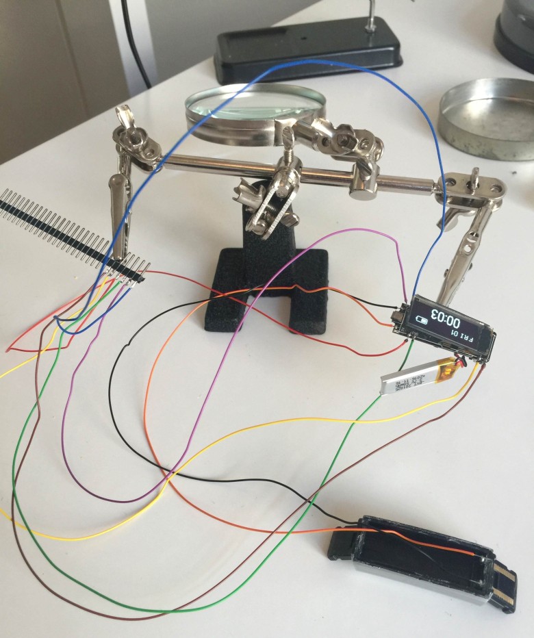
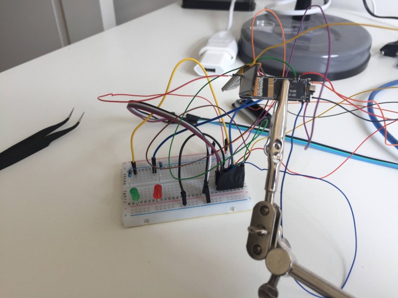
Having gained access to two SWD pads, I soldered very fine wiring to them and to all other available contacts.
We blink a bit
The next task is to try to program the device for any task. To run the simplest program, we need to make sure of the following:
- We correctly traced the contacts SWDIO / SWDCLK.
- The SWD programmer is running and the computer can issue commands.
- We can compile the Arm program and use the Nordic SDK correctly.
- We can flash the compiled program into the chip.
- The chip works correctly and loads our program.
In this case, the program that turns on and off the LED can act as “hello, world”. And even this is not elementary, because the board does not have a built-in LED, and if you add an external one, you still need to figure out what to connect it to. This adds another dimension to the spatial model of the problem. According to the absence of free cheese theorem, I simply connected two LEDs to contacts
P1 and
P2 with the hope that we could get to these contact pads with the MCU.
 Bad Wire Day
Drivers and command line programs for the J-Link SWD programmer are on
the Segger site . If you're on macOS and using Homebrew, then look for the Cask formula in
caskroom/drivers/segger-jlink . Communication with the SWD programmer is established from the
JLinkExe command line
JLinkExe .
Then I downloaded the
Nordic nRF5 SDK (I am using
version 12.3.0 ). From the examples of the SDK, it is clear that we will need a compiler capable of compiling Arm programs. Therefore, I also installed
gcc-arm-embedded (also available at Homebrew).
After reviewing the SDK documentation and the Nordic developer forums, I found out that their SDK is most often used with development boards
like this . The SDK is preconfigured for several variants of such cards. Since we are contacting directly with the controller, we will have to configure some parameters of the SDK.
I spent a
lot of time understanding the nRF5 ecosystem, but in the end I was still able to run a program on a chip! The
video shows two flashing LEDs. At this stage, I created
the Github repository and dropped the program with the worker
Makefile . One of the most important secrets was that in fact there are several options for nRF51822, and in my only 16 KB of memory. So I had to
tweak the linker script .
Digital I / O
As I said before, the task with flashing LEDs provided for some hope and a poke method, which of the MCU pins lead to
P1 and
P2 , where the LEDs are connected. The simplest strategy is to connect all the leads one by one and alternately apply high and low voltages. To my surprise, both LEDs lit up! I was even more surprised when I started the vibrator!
So, the spear method added the table:
| NRF51822 output | Playground | Description |
|---|
| P0.30 | P1 | Digital GPIO |
| P0.00 | P2 | Digital GPIO |
| P0.01 | - | Vibration motor |
printf
The ability to transfer data to a computer is irreplaceable when debugging. The J-Link programmer supports
real-time transfer (RTT) for both sending and receiving data from a chip. To use RTT, you need to
#include "SEGGER_RTT.h" and call
SEGGER_RTT_WriteString() . To get data on your computer, call the command line
jlinkrttlogger , which comes bundled with J-Link.
OLED
Another challenge is to get OLED to work. In the most common OLEDs, the
ssd1306 driver / controller works on the market, and usually the communication with the MCU is carried out via a serial interface using either
SPI or
I²C . Here is
an example from Adafruit .
I have not found such a display in any of the usual stores. And the size of 96 × 32 is non-standard. Search by ID QT1316P01A on the display gives Chinese sites such as
Aliexpress , but there is no documentation other than the names of the findings:
 Naming pin OLED with Aliexpress
If the list is not lying, then the contacts
SCL ,
SDA and
RES# indicate to us that this is an I²C variant. If the tracks are between the three pins of the nRF51822 and these three pins of the OLED, then we will take a step forward. Let's go back to the microscope.
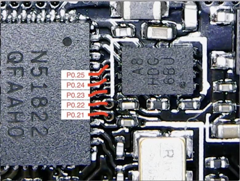
 OLED Data Contact Tracks
Update the match table:
| NRF51822 output | Playground | Description |
|---|
| P0.21 | - | OLED SDA output |
| P0.22 | - | OLED SCL output |
| P0.24 | - | Output OLED RES # |
I²C is much more advanced than any simple serial protocol like
UART . One of the advantages is that it supports multiple master and slave devices on the same bus. This complicates matters a little: at a minimum, you need to tell the MCU for which slave commands are given. So, on a high level, apart from the physical contacts, there is also a “logical” address of the OLED display.
Fortunately, one of the examples in the nRF5 SDK is the I²C scanner. He polls with all possible logical addresses and reports if something is installed there. My modified version is
here . He gives this log:
$ make
# ...
$ make flash
# ...
$ make log
# ...
TWI scanner.
TWI device detected at 0x3c.
Great news! We have good reason to believe that the display is correctly identified and it is indeed an I²C variant. A Google search says that
0x3c is a typical address for such devices.
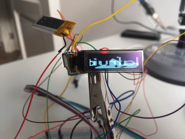
Now we are ready to send some pixels to the display. At this level, there is no abstraction through the library.
See the ssd1306 documentation for a low-level data transfer method. A process consists of a sequence of configuration commands that set the display orientation, recording mode, size, etc. Then a sequence of bytes is sent to the graphics display memory (GDDRAM), which are displayed on the screen.
For the correct configuration, I studied
the ssd1306 library from Adafruit and tried to emulate similar commands. This is exactly what the lion's part of time spent on this project. It turned out to be very time-consuming to learn all the details, and still I cannot explain some things. However, it works!
 Display hard-coded raster pattern
The code for this example is
here .
With these settings, the display is divided into 4 lines (pages) and 96 columns. So pages are 8 pixels high. The first byte sent will be placed “vertically” in the first column of the first page. The second byte will take the second column, then the third and so on, up to the 96th column, when it
comes back and starts from the first column on the second page.
This is the
expected behavior. As
shown in the video , the
observed behavior is different: first, odd columns are filled, then even, and then it returns to the second page.
I spent a lot of time to understand the reason for such a stupid display behavior, and then some more time for setting up the configuration to fix it. In the end, I swallowed my pride and nevertheless implemented such a strange rendering logic in the program to finish on this.
Travel to the country of Arduino
Delving into
the Adafruit ssd1306 library for Arduino, I thought all the time that it would be nice to have a way to "imitate" Arduino specific bits to test them on nRF51822. It turns out that much more experienced people also thought on this topic - this is exactly what makes the amazing project
sandeepmistry / arduino-nRF5 . It implements the core Arduino libraries using the nRF5 SDK.
With this project, we can open the Arduino IDE, choose the nRF5 board - and use the rich Arduino ecosystem. I
forked the project and added support for the board from our bracelet. You can select it in the
Tools > Board > ID115 Fitness Bracelet (nRF51822) drop-down menu
Tools > Board > ID115 Fitness Bracelet (nRF51822) .
 Adafruit ssd1306 library in its original form (above) and with the patch (below)
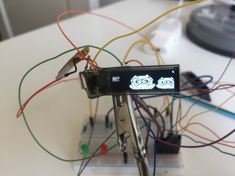
This also means that we can now use
Adafruit's OLED library . To my surprise and relief, the same strange behavior occurred with the filling of odd first and then even OLED columns! I gladly
forked the library and implemented the same hack. Compared to the low-level approach, we now have access to a variety of cool abstractions, for example, text output:
 More familiar “Hello, world!”
Analog I / O
In addition to digital on / off signals, the nRF51822 has 10 pins for analog input. This is useful, for example, to read the current battery charge. Judging by the documentation, reading analog contacts produces a 10-bit value. Therefore, if the input is
0V , then we will read
0 , and if there is a
VCC , we will read
1023 with intermediate values between them.
I periodically read the values of the analog inputs and plotted the most interesting signals:
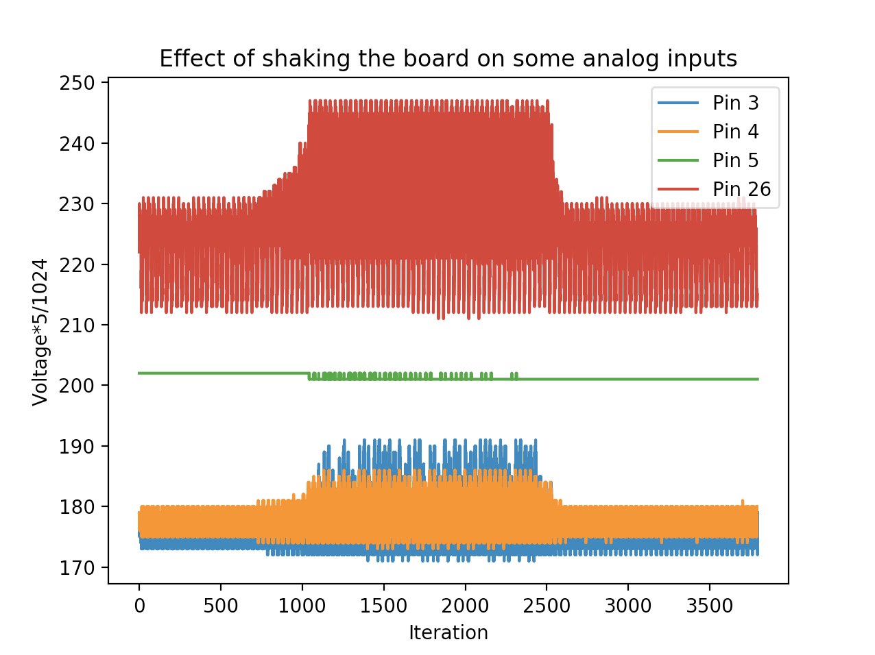
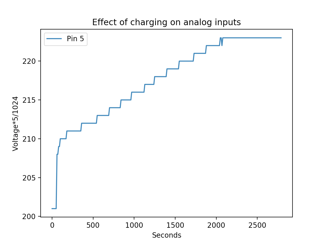 The effect of shaking the board and charging the battery with data from analog inputs
I am convinced that contact
P0.05 refers to the charge of the battery, because the value increases and decreases as it is charged and discharged. I suspect that contact
P0.26 connected to one of the outputs of the accelerometer, as it goes crazy when the board is shaken. Contacts
P0.03 and
P0.04 can also be connected to different accelerometer outputs, but here a certain second-order effect is most likely superimposed on the signal from the input. For example, in the first chart, notice how the battery level (pin 5) changes when the accelerometer needs more energy. This is an example of a second order effect.
The code can be found
in this sketch . Source data and plotting script
here . Now you can add a few lines to our lookup table:
| NRF51822 output | Playground | Description |
|---|
| P0.05 | - | Analog input - connected to battery charge |
| P0.26 | - | Analog input - one axis accelerometer |
| P0.03 | - | Analog input - one axis accelerometer (probably) |
| P0.04 | - | Analog input - one axis accelerometer (probably) |
Button
In the original firmware, touching the bracelet at a certain point turns on the display. When you hold this point, the chronometer starts, if I remember correctly. This is not a physical button, but some kind of capacitive sensory thing that works surprisingly well. Using the same approach as searching for digital outputs, I
found a place to connect to the MCU (video) .
The code is
here .
| NRF51822 output | Playground | Description |
|---|
| P0.10 | - | Digital input - built-in button |
Bluetooth low energy (BLE)
The BLE functionality on nRF5 chips is implemented through something called
SoftDevice . This is a precompiled binary file with a stack of BLE. It is stitched regardless of the application. There are many versions of SoftDevice, depending on the version of the SDK and the version of the chip.
The
documentation provides a certain dependency matrix (unfortunately, you cannot put a direct link to it). It shows which SDK the different versions of the chip come from - and what the SoftDevice version stands there. In our case, the chip is marked QFAAH0, this chip has 256 KB of flash memory, 16 KB of RAM and is declared compatible with SoftDevice s130.
My SDK version 12.3 already contains several examples of using SoftDevice s130. Compared to previous programs that are directly sewn into chips from address
0x0 , now you need to flash SoftDevice from address
0x0 , and the program itself from address
0x1b000 . After downloading and initialization, the SoftDevice binary file will go to this address and transfer control to our program. To illustrate, I took the same example with blinking LEDs, but changed it for SoftDevice firmware (
code ). The observed behavior has not changed, unless you need to flash SoftDevice in advance:
$ make
# ...
$ make flash-softdevice
# ...
$ make flash
# ...
$ make log
# ...
Hello, world!
Perhaps the simplest Bluetooth app is turning your device into a
beacon . The device only broadcasts its presence. One such example is in the SDK called
ble_app_beacon . He assumes that SoftDevice
s130 already flashed.
Here, too, low-level communication with the chip complicates things compared to programming via the SDK. In addition to adjusting the size of the RAM (this knowledge was hard for me in the example with LEDs), another difficult problem to be monitored came to light. As it turned out, the BLE stack uses a clock generator to perform time-sensitive tasks. The SDK examples assume an external crystal oscillator. When I realized this after thousands of attempts to
printf , I changed the configuration flag to use a synthetic clock generator, and the problem was solved. The source code of the beacon is
here .
Ble + arduino
When the BLE example worked with the nRF5 SDK, knowing about the RAM and generator traps, I again looked at the Arduino environment. And again, there was the glorious
sandeepmistry / arduino-BLEPeripheral project (from the same guy as arduino-nRF5!), Which provides excellent abstractions over the top of the internal BLE setup.
To my surprise, I did not even have to fork the library. The author of the arduino-nrf5 project spent time and added the configuration of all boards and settings, so now choosing the right clock generator for SoftDevice comes down to a simple choice from the
Tools > Low Frequency Clock > Synthesized drop-down menu. Awesome I quickly wrote
an example with the inclusion of a green LED via Bluetooth (with
this application ). His work is
shown in the video .
Future plans
After messing around with this board for countless hours for a few weeks, itching to shove her away from the washing machine and forget for a while.