Fuzzy logic to control
The text was prepared on the basis of materials from the book by Gostev V.V. “Fuzzy controls in automatic simulation systems”. Like all serious publications on the topic, this book is overloaded with mathematical calculations and difficult for an unprepared reader. Meanwhile, in themselves, the principles of creating and using fuzzy logic are quite simple and intuitive. This text is an attempt to translate an example from a book from a mathematical language to engineering.
A possible sequence of designing a controller based on fuzzy logic is shown by sequentially complicating logical rules and selecting parameters by optimization methods.
Formulation of the problem
Consider the synthesis of a digital PID controller and a fuzzy controller for a rocket control system with respect to the angle of attack. By the method of mathematical modeling, we will determine the processes in the system and give a comparative assessment of the quality of the system using synthesized controllers.
Taking the angle of attack for the output coordinate of the rocket:  , and for the input coordinate steering angle
  we define the transfer function of the rocket in the form:
 where:
 - the conversion rate of the rocket,
 - damping ratio,
 - time constant.
Hereinafter, the “transfer function” is used not in the strict classical definition, as the ratio of Laplace transforms.
In the study of the control system, we assume that the dependence of the parameters of the rocket on the flight time are determined as follows:

To simplify the calculations, the steering mechanism will describe the transfer function of the integrating link.  In this case, the system input
  - given angle of attack, system output - the angle of attack developed by the rocket, m (t) is the control signal at the regulator output, and the control object is described by a common transfer function:

(The control object includes an analog steering gear and a rocket).
The law of change in input is given by a polynomial:

It is necessary to develop a regulator that ensures the processing of input effects using a PID controller and a controller based on fuzzy logic.
To carry out the selection of coefficients of regulators.
Make a comparison of the transition process with a PID controller and a controller based on fuzzy logic.
Dynamic object model
Create a dynamic model in the environment of structural modeling.
The scheme of the model itself is presented in Figure 1.
The specified effect is set in the form of a constant block, and the variable from the script is set as parameters. The parameters of the transition function are set as variables.
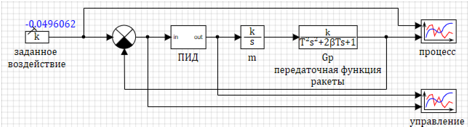 Figure 1. Diagram of a dynamic model of a rocket.
Regulator setting
The PID block is a submodel (Fig. 2), which uses the standard block "Discrete PID controller". The sampling rate is chosen to be 0.001 sec.
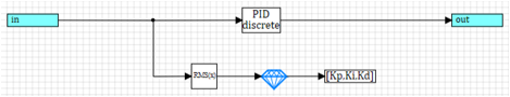 Figure 2. PID controller with a tuning scheme.
Regulator parameters are specified as names of global signals of the project
Kp, Ki, Kd. This allows you to change the parameters during the simulation, and adjust the controller.
The
“Optimization” block was used to adjust the regulator, the optimization criterion is the minimum of the standard deviation.
The optimization unit performs optimization throughout the transition process. The result of optimization is a vector of three coefficients, which is sent to the “Recording to the signal list” block, where the calculated values are transferred to the signals and, accordingly, the values of the PID coefficients change. To configure the controller, we set the following optimization parameters:
The initial values of all coefficients are
1.Range for selection is set from
-50 to
+50Accuracy of selection
0.001Maximum standard deviation after optimization
0.01In this case, the optimization block calculated the following optimal coefficient values:
Kp = -1.7498597; Ki = 17,891995; Kd = 11.606602 .
With such coefficients, the standard deviation in a given transient process was
0.008738090
Figure 3. Transition.
| 
Figure 4. Management. |
Fuzzy Controller
The main advantage of the regulator based on fuzzy logic is the simplicity and clarity of the formation of rules for controlling an object.
For example, in the book “Fuzzy Controllers in Automatic Simulation Systems”, the rules of fuzzy regulation for controlling a rocket by angle of attack are described in the form of a mathematical expression:

Where,

- system error, speed changing (first derivative) errors, acceleration (second derivative) errors;
m - control effects on the object;

- linguistic estimates of the error, the rate of change of the error (first derivative) of the error and the second derivative of the error, considered as fuzzy sets, defined on the universal set

;

- linguistic evaluation of the control action on an object, selected from term sets of the variable
mThe reader may ask: how is it, your mother, sorry, understand?
Sometimes I doubt that authors of mathematics themselves understand what they have written. Behind the abstruse mathematical turns hidden the great mystery of the rules of fuzzy regulation. Here she is:
many - reduce
norm - do not touch
little - increaseIf you translate from the bird language of mathematics into Russian, the expression

means literally the following:
If
more than the norm and the
deviation increases and
the growth rate increases , then
decrease .
If the
norm does not change and the
speed is constant , then we
do not change .
If it
falls below the norm and the
fall speed increases , then we
increase .
If you understand what is really hidden behind the math foggy, then you can approach the creation of regulators more consciously and get more interesting results.
Some theory
To solve the problem of controlling the angle of attack, we need to obtain three terms from a continuous deviation value - less, norm, more. The same must be done for the first derivative of the deviation and the second derivative of the deviation. This is the first stage of fuzzy inference - phasing.
To obtain terms, we must specify a numeric parameter value for each term. For example: “Little” = -1; "Norm" = 0; “Many” = 1. For phasing we will use triangular functions. Functions grow as you approach a predetermined value, and decrease as you move. Two variants of triangular functions are shown in Figure 5:

 Figure 5. Triangular membership functions.
Knowing the magnitude of the deviation (x1), we can find the values of the membership function for terms more (red line), norm (green line), less (blue line). Values will be in the range of 0 to 1.
Note that in the left graph, the extreme functions are not quite “triangular”. If we consider from the point of view of abstract mathematics, then the functions on the right graph are more “beautiful”. But, if we recall the “main secret of the rules of fuzzy inference,” then the left graph is more correct. Indeed:
Consider the rule
“Not enough - add” , if we have a value of -1, then
“little” = 1 (red line) is true for both graphs. And if we have a value of -2? Logically, we also have to
"add .
" On the left graph at -2, it is:
“little = 1” , but on the right graph, we have
“little” = 0, which is obviously not true. The same is true for the rule
“Reduce a lot” .
Phasing by “honest” triangular functions can lead to the fact that when a value goes beyond the range of definition of functions, we get 0 for all terms, which, in turn, can lead to the absence of an impact on the object.
The inverse problem is dephasing. To calculate the impact, you need to perform the inverse transformation - we have the values of the membership functions to reduce, not to change, to increase in the range (
0 ... 1 ) (triangular functions) and the range of effects that we can have, and we must get one of the three terms number - specific impact.
You can get the impact in various ways, for example, in the center of mass of the figure. Figure 6 shows the state of the regulator, where the values of the terms decrease
0.3 do not change
0.6 and increase
0.8 with the regulatory action range
-30..30 resulting impact =
4.1.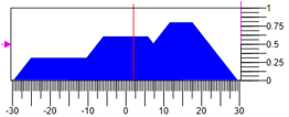 Figure 6. De-Phasing Control
Another variant of dephasing is in the center of mass of the points. Figure 7 shows the variant, where for the same values of terms and range of regulation, we get another answer
8.82 :
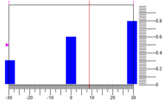 Figure 7. Dephasification by the center of mass of points.
It should be understood that in addition to the output method, the shape of the membership function also affects the result. For example, you can choose such triangular functions, in which the base of the triangle is the same, only the vertices differ. (see fig. 8).
 Figure 8. Triangular functions with one base.
In this case, the result of phasing at the same values of terms should be reduced to 0.3, not to change to 0.6 and to increase to -0.8 with a range of control action of -30, 30 resulting impact =
5.27 .
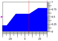 Figure 9. Dephasing method of calculating the area.
Armed with secret knowledge of fuzzy logic, create a model of the regulator. The model of the rocket is left the same as for the PID controller (see Fig. 1), but in the submodel of the controller we will assemble the circuit shown in Figure 10.
 Figure 10. Controller circuit based on fuzzy logic.
The input to the regulator is the mismatch between the specified angle of attack and the real (measured). After the input, there is an “Extrapolator” block, which provides the conversion of a continuous signal to a discrete one with a given sampling period (0.001 s — the same as that of a discrete PID controller).
After that, the calculation of the first and second derivatives of the deviation. To do this, we calculate the difference between the current value and the value with a delay for the quantization period, divide it by the delay time (the coefficient in the comparison block). Thus, we get three inputs: system error, rate of change (first derivative) errors, acceleration (second derivative) errors.
The value of the input variables are converted by phasing units with triangular functions. For each variable, we obtain three linguistic variables (nine in total).
The demultiplexer blocks divide vectors into linguistic variables to form rules. On the diagram, the names of the variables are signed in order of their order in the vectors.
The deviation in our case is the difference between the target and the measured, if a negative value means the angle of attack is greater than the target, we should reduce it. And accordingly, on the contrary, if the deviation is positive, then the measured angle is less than the specified one, we must increase.
(More - reduce, less - increase, norm - do not touch) .
The output also has three linguistic variables "reduce", "do not change", "increase". The multiplexer collects the values in a vector and gives it to a fuzzy output block. Now that we have all the variables, we can write the rules for fuzzy inference in the form of a schema.
- If more than the norm and the deviation increases and the growth rate increases => decrease.
- If the norm does not change and is constant => we do not change.
- If it is less than the norm and falls and the fall rate increases => we increase.
All the linguistic variables in the rules are connected through logical “and” blocks and connected to the outputs. As can be seen from Figure 10, the logic circuit of a fuzzy inference does not practically differ from the usual logic circuit, only blocks of fuzzy logic are used.
Similar to setting up a PID controller, we use an optimization block.
The question remains with the parameters of the blocks.
Fuzzy logic controller synthesis
In life, nothing is given freely and therefore, the simplicity of the regulation rules is compensated by the number of parameters describing the membership functions. In fact, if for the PID controller you need to choose three coefficients, in the case of fuzzy logic, only one triangular function needs 3 numbers for the vertices. If for each input variable we need 3 membership functions + 3 for the output, it turns out that we need to set 3 x 3 x 3 + 3 x 3 = 36 parameters!
But not everything is so sad. For the first approximation and initial setup, you can simplify everything.
Having made some assumptions for the initial adjustment of the regulator:
- We define the symmetry of the functions with respect to zero, then instead of two numbers for the maximum and minimum, one can be specified - Mach , and, accordingly, the range will be defined as [ -Max ... Mach ].
- We assign a uniform distribution of functions, then we can calculate the position of all the vertices of the triangles from the specified range.
- For the three functions, the coordinates of the vertices are defined as –Max, 0, Max.
- We specify that the base of the triangle of all membership functions is the same.
Thus, instead of 36 independent parameters, we need to specify only 4, the maximum deviation from 0 for three input variables and one output, namely:
uMax - control amplitude
(-uMax ... uMax) ;
deltaMax - maximum deviation
(-deltaMax ... deltaMax) ;
divMax - the maximum derivative of the deviation
(-divMax ... divMax) ;
div2Max - maximum second derivative of the deviation
(-div2Max ... div2Max)In the functions of phasification and fuzzy inference, we use these signals to calculate the parameters taking into account the accepted assumptions.
Controller settings proposed in the book Gostev V.V. “Fuzzy regulators in automatic modeling systems”, for the case of phasing with three membership functions, the following parameters are proposed:
uMax = 30 - control amplitude;
deltaMax = 0.01 - maximum deviation;
divMax = 0.07 - the maximum derivative of the deviation;
div2Max = 1 is the maximum second derivative of the deviation.
Transient Comparison
On the transient graph, the coincidence of a given effect and the result obtained is almost complete:

Figure 11.a Transition. PID controller
| 
Figure 11.b Transition. Fuzzy logic
|
Obvious differences can be viewed on the graphs of the resulting deviation and control action:

Figure 12.a. Control. PID controller
| 
Figure 12.b. Control. Fuzzy logic |
Comparing the figures shows that a fuzzy controller provides a smaller error, and it is better to work out the transition process.
Compare the transients in the system, if you specify a stepped control action. The results in Figure 13:

Figure 13.a. Step impact. PID regulator.
| 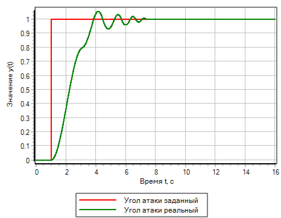
Figure 13.b. Step impact. Fuzzy logic. |
For step effects, the controller based on fuzzy logic provides the best quality of the transition process. The PID controller, which is automatically tuned to a smooth process, causes oscillations with overshoot twice the predetermined step.
Configuring the controller based on fuzzy logic optimization method
Let's try to select the parameters of the fuzzy controller using the optimization method, just as we selected them for the PID controller. As a criterion, we set the standard deviation less than 0.001.
It should be noted that this method is not entirely correct, because for professionals it is clear which angles and speeds are maximum and minimum for each concert product, which allows you to set constraints on optimized parameters more consciously, we set the default parameters and see what happens.
The optimization method with default settings calculated the following values of the optimization parameter ranges:
uMax = 19.377 is the amplitude of the control action;
deltaMax = 1.095 - the maximum deviation;
divMax = 0.01 - the maximum derivative of the deviation;
div2Max = 2.497 is the maximum second derivative of the deviation.
In the case of a simple optimization by deviation, the obtained parameters provide the specified accuracy, however, at the same time, they cause high-frequency oscillations of the control action.
Transitional function and control actions are presented in Figure 14.a
 Figure 14.a. Fuzzy logic. Deviation setting. Figure 14.a. Fuzzy logic. Deviation setting.
| 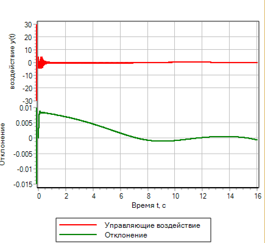 Figure 14.b. Fuzzy logic. Setting the deviation and the number of operations. Figure 14.b. Fuzzy logic. Setting the deviation and the number of operations. |
In order to improve the transition process, you can add to the optimization criterion the number of switchings of the regulator from negative to positive value of the regulating influence (diagram in Fig. 15).
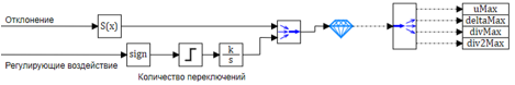 Figure 15. Scheme for optimization by 2 criteria.
The calculation by the method of optimization according to two criteria gives the following parameter values:
uMax = 19.714 - control amplitude;
deltaMax = 1.0496 - the maximum deviation;
divMax = 0.01 - the maximum derivative of the deviation;
div2Max = 1.7931 is the maximum second derivative of the deviation.
It can be seen that when adding the number of positives to the criterion, it was possible to reduce the switching frequency of the regulator (see Fig. 14.b). Thus, it can be said that the optimization method works even when we know nothing about the physics of the object and just select the numerical parameters without thinking about their physical meaning.
Creating your own controller based on fuzzy logic
Above, we created a regulator using a ready-made and fairly simple scheme, all terms of linguistic variables were connected by a logical operator I. Since we have the same number of terms at the inputs and outputs, this is the simplest and most obvious solution.
Let's try to make a regulator whose output does not have 3 terms, but, for example, 5:
reduce quickly, decrease, not change, increase, increase quickly . And the input is the same.
Let's change the logic of the regulator, to start with the most simplified control algorithm.
We write the rules:
1) If
more and grow t
=> decrease quickly.2) If
more => decrease.3) If the
norm => do not change.4) If
less => increase.5) If it is
less and has
less => increase quickly.In this case, we have 5 terms for the output variable (5 triangular functions). We accept that they are equally spaced between
-uMax and + uMax.We assume that the triangular functions are composed in such a way that when the membership functions of a term take on maximum values, the neighboring functions take on zero values (see Fig. 5).
As parameters for output, only deviation and rate of change of deviation will be used.
To speed up the calculations, we use the phase determination of the method by the center of gravity of the points (see fig. 7).
In this case, the regulator circuit will look as shown in Figure 15.
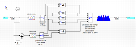 Figure 15. Simplified controller based on fuzzy logic.
Instead of the range of the second derivative of the optimizer, the term for the term “increase” will be queried. An attempt to set up such a regulator using the optimization method shows that the regulator is being adjusted, but the quality of regulation of system control leaves much to be desired.
The best result is shown in Figure 16.
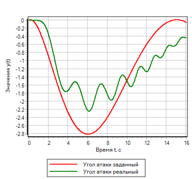 Figure 16. Transient for simplified controller.
It can be seen that the regulation occurs, but not at all as we would like. The point is that we make an impact when a deviation has already occurred. Let's try the inclusion of regulation at the moment when we have a deviation in the norm, but the speed shows that it will increase or decrease.
1) If
less and decreases => increase quickly.2) If the
norm and increases => decrease.3) If the
norm => do not change.4) If the
norm and decreases => increase.5) If
more and grows => decrease quickly.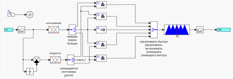 Figure 17. Control of the rate of change of deviation.
The results of the regulator adjusted by the optimization method are presented in Figures 18a and 18b.

Figure 18.a. The transition process.
| 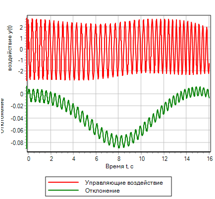
Figure 18.b. Control |
Control of the rate of change of deviation significantly improved the transition process. However, if you look closely at the set of logical rules, we see that the deviation does not participate in the control. If given a stepped effect, the control controller will not generate a control action. Fig. 19 shows an example of a transient process with a stepped control action, it can be seen that the controller does not issue a control action, although the deviation is 1.
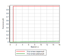
Figure 19.a. The transition process. Step
| 
Figure 19.b. Control. Step |
In order to work out the fast deviations, add the control action when the deviation. We will increase if less and decrease if more. Since there are already rules in the rule set for which we reduce and increase, we use a logical operator or:
1) If
less and decreases => increase quickly.2) If (the
norm increases )
or more => decrease.3) If the
norm => do not change.4) If (the
norm and decreases )
or less => increase.5) If
more and grows => decrease quickly.The regulator circuit according to these rules is presented in Figure 20.
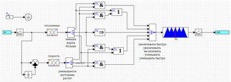 Figure 20. Regulator with control of deviation and rate of change.
As a result of the modification, the quality of the transient process with a smooth effect practically did not change, however, with a stepwise effect, the regulator began to work out the step and reduce the angle of attack of the rocket to the target (see Fig. 21).
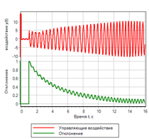
Figure 21.a. The transition process. Step
| 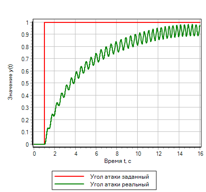
Figure 21.b. Control. Step |
In conclusion, let us once again “improve” our regulator.
Let's try to use the second derivative of the deviation, to start the impact, before the deviation and its speed have changed. In fact, with the application of force, we have an acceleration to which we can already react.
Let's try to add to the law of regulation instead of the first derivative of speed, the second derivative. We will have an additional regulating effect in the case when our second derivative shows that there will be a deviation.
The general rules will look almost the same, only in brackets we have three terms, deviation and speed are normal, and the second derivative deviates:1) If it is less and decreases => increase quickly.2) If ( rate and constant and dispersed ) or greater => decrease .3) If the norm => do not change.4) If ( rate and constant and decelerates ) or less => increase.5) If more and growing => decrease quickly .The scheme of this regulator is shown in Figure 22. To save space on the diagram, the logical expressions “and” written in the rules in brackets are calculated in the submodel labeled “ & ”.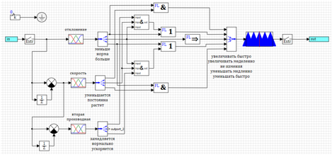 Figure 22. Fuzzy logic controller with control of the second derivative.After the selection of parameters by the optimization method for the deviation and the number of inclusions, the following parameters were obtained:uMax = 27.4983 - control amplitude;deltaMax = 0.0433 - the maximum deviation;divMax = 0.0966 - the maximum derivative of the deviation;div2Max = 1.0828 is the maximum second derivative of the deviation.The transition process is shown in Figure 23. It can be seen that the resulting regulator has the best performance of all those considered above, but for a given effect. Deviations and control actions - the smallest of all considered in this text.
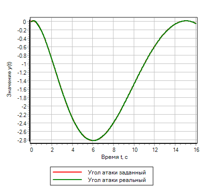
Figure 23.a. The transition process.
| 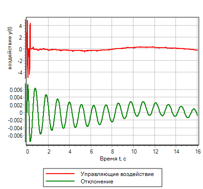
Figure 23.b. Control. |
findings
A fuzzy logic controller can provide a higher quality transition process for controlling a missile than a PID controller.Adjusting the controller based on fuzzy logic can be done by means of optimization.A fuzzy logic controller provides greater flexibility in tuning and better quality of the transition process. But it requires setting more parameters.Download the archive of models used in the preparation of this text for self-study here ...