Night vision device based on the Flir Lepton 3 thermal imaging module

Earlier, I wrote an article about connecting to a computer a thermal imaging console to the Flir One Gen 2 smartphone. It’s time to remove the lepton module from this console and connect it directly to the microcontroller by assembling a night vision device with a resolution of 160x120 pixels.

To build your own night vision thermal imager, you will need:

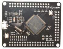
1) Board with a microcontroller. I took a fee from the Chinese comrades with the STM32F407VGT6 microcontroller. Good such a controller: 168 MHz frequency and 192 KB of RAM.


2) Display. I took the display with a resolution of 320x240. Such displays are available with different controllers. I got with the hx8347d controller.


3) A board for connecting a lepton 3 on SPI and I2C.


4) The lepton itself 3. The most difficult and expensive element. To get it, I bought a faulty thermal imager Flir One Gen 2 on ebay and took out a lepton from it. In magnification it looks like this:


Point 3 can be excluded from this list, if, of course, you manage to get a bed for a lepton from a faulty thermal imager and you can unsolder it (and her contacts, by the way, will be from the bottom). Unfortunately, the distance between the legs of the lepton is quite small, so this option did not obey me.

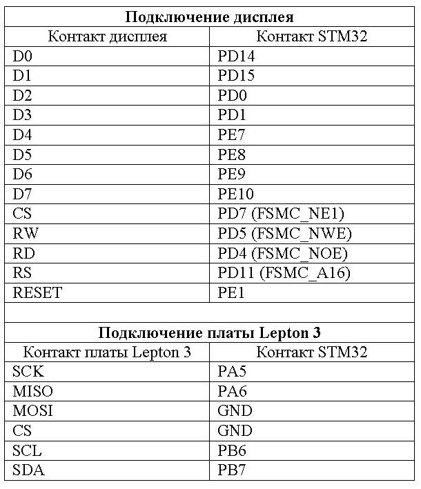
To collect all this, you just need to solder all this as follows:


Also need to connect the power. To power the lepton board, I use 5 V, for the STM32 3.3 V board. To get 5 V from the battery, I use a TEL3-0511 converter (input voltage from 4.5 to 9 V), and already I lower this 5 V on an ordinary LP2950CZ-3.3 (by the way , it heats up to 70 degrees. There would also need to use a DC / DC converter, but I haven’t bought it yet). Eat lepton 3, by the way, good. When powered from 6 V, the current consumption of the entire device is about 250 mA. When the lepton wants to click the curtain for calibration, the current rises to 500 mA.

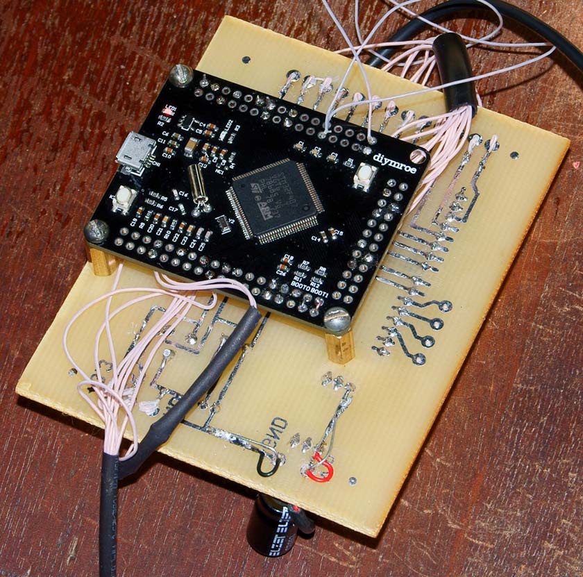
All together it looks like this:


To work with a lepton will need a program. I used CubeMX and Keil 5. In this case, the entire software binding is simplified to impossibility.

Communication with a lepton is carried out by SPI. I have not used I2C yet, as there was no special need for it. Using I2C, you can control the state of the lepton, its modes of operation, enable / disable the automatic calibration mode, and so on. But for the night vision device is not particularly necessary.

To decrypt the data, I wrote a module:

Module
leptoncontrol.h
#ifndef LEPTON_CONTROL_H #define LEPTON_CONTROL_H #include <stdbool.h> #include <stdio.h> //   ( ) #define LEPTON_ORIGINAL_IMAGE_WIDTH 160 #define LEPTON_ORIGINAL_IMAGE_HEIGHT 120 //  VoSPI #define VOSPI_FRAME_HEIGHT 60 //  VoSPI #define VOSPI_FRAME_WIDTH 80 //  VoSPI   (164  RAW14  244  RGB) #define VOSPI_PACKAGE_SIZE 164 //   VoSPI   #define VOSPI_PACKAGE_LINE_SIZE 160 //  VOSPI   #define VOSPI_SEGMENT_LINE_AMOUNT 60 void LEPTONCONTROL_Init(void);// void LEPTONCONTROL_CalculateCRC(unsigned short *crc,unsigned char byte);// crc bool LEPTONCONTROL_PushVoSPI(unsigned char data[VOSPI_PACKAGE_SIZE],bool *first_line);//    VoSPI    unsigned short *LEPTONCONTROL_GetRAW14Ptr(void);//      #endif 

leptoncontrol.c

 #include "leptoncontrol.h" #include "stm32f4xx_hal.h" static unsigned short RAW14Image[LEPTON_ORIGINAL_IMAGE_HEIGHT*LEPTON_ORIGINAL_IMAGE_WIDTH];//  static unsigned short CRCTable[256];//   CRC16 //     #define RESYNC_TIMEOUT_MS 19 //:   #define NO_SEGMENT -1 //:   #define ERROR_PACKAGE -2 //---------------------------------------------------------------------------------------------------- // //---------------------------------------------------------------------------------------------------- void LEPTONCONTROL_Init(void) { //    CRC unsigned short code; for(long n=0;n<256;n++) { code=((unsigned short)n)<<8; for(unsigned char m=0;m<8;m++) { if(code&(1<<15)) code=(code<<1)^0x1021; else code=code<<1; } CRCTable[n]=code; } } //---------------------------------------------------------------------------------------------------- // crc //---------------------------------------------------------------------------------------------------- void LEPTONCONTROL_CalculateCRC(unsigned short *crc,unsigned char byte) { *crc=CRCTable[(((*crc)>>8)^byte++)&0xFF]^((*crc)<<8); } //---------------------------------------------------------------------------------------------------- //---------------------------------------------------------------------------------------------------- long LEPTONCONTROL_ReadSegment(unsigned short *raw14_ptr,unsigned char data[VOSPI_PACKAGE_SIZE],bool *first_line) { static long current_package=-1; static long segment=-1; long n; *first_line=false; if ((data[0]&0x0F)==0x0F) return(NO_SEGMENT);//  unsigned short crc=data[2]; crc<<=8; crc|=data[3]; // CRC unsigned short crc16=0; LEPTONCONTROL_CalculateCRC(&crc16,data[0]&0x0F); LEPTONCONTROL_CalculateCRC(&crc16,data[1]); LEPTONCONTROL_CalculateCRC(&crc16,0); LEPTONCONTROL_CalculateCRC(&crc16,0); for(n=4;n<VOSPI_PACKAGE_SIZE;n++) LEPTONCONTROL_CalculateCRC(&crc16,data[n]); if (crc16!=crc) return(ERROR_PACKAGE);// CRC //   unsigned short package=data[0]&0x0F; package<<=8; package|=data[1]; if (package==0) { *first_line=true; current_package=0; } if (package==20) { unsigned char ttt=(data[0]&0x70)>>4;//     20  segment=ttt; } if (current_package<0) return(NO_SEGMENT); if (current_package!=package) { current_package=-1; return(ERROR_PACKAGE); } unsigned short *raw_ptr=raw14_ptr+current_package*VOSPI_PACKAGE_LINE_SIZE/2; for(n=0;n<VOSPI_PACKAGE_LINE_SIZE/2;n++,raw_ptr++) { //    big-endian: ,  unsigned short value=data[n*sizeof(short)+4]; value<<=8; value|=data[n*sizeof(short)+5]; *raw_ptr=value; } current_package++; if (current_package!=VOSPI_FRAME_HEIGHT) return(NO_SEGMENT); current_package=-1; return(segment); } //---------------------------------------------------------------------------------------------------- //    VoSPI    //---------------------------------------------------------------------------------------------------- bool LEPTONCONTROL_PushVoSPI(unsigned char data[VOSPI_PACKAGE_SIZE],bool *first_line) { *first_line=false; static long waitable_segment=1; long segment=LEPTONCONTROL_ReadSegment(RAW14Image+(waitable_segment-1)*VOSPI_FRAME_WIDTH*VOSPI_SEGMENT_LINE_AMOUNT,data,first_line); if (segment==ERROR_PACKAGE) HAL_Delay(RESYNC_TIMEOUT_MS); if (segment==ERROR_PACKAGE || segment==0) waitable_segment=1; if (segment==ERROR_PACKAGE || segment==NO_SEGMENT || segment==0) return(false); if (segment!=waitable_segment) { waitable_segment=1; if (segment!=1) return(false); } waitable_segment++; if (waitable_segment!=5) return(false); waitable_segment=1; return(true); } //---------------------------------------------------------------------------------------------------- //      //---------------------------------------------------------------------------------------------------- unsigned short *LEPTONCONTROL_GetRAW14Ptr(void) { return(RAW14Image); } 


All work with this module is to simply submit the data obtained by SPI.

Work with the module
 while(1) { //   while(1) { HAL_SPI_Receive(&hspi1,buffer,VOSPI_PACKAGE_SIZE,0x1000); bool first_line=false; unsigned char *buffer_ptr=buffer; LEPTONCONTROL_PushVoSPI(buffer_ptr,&first_line); if (first_line==true) break; } //    lepton3 unsigned char *buffer_ptr=buffer; HAL_SPI_Receive(&hspi1,buffer_ptr,VOSPI_PACKAGE_SIZE*SPI_READ_VOSPI_AMOUNT,0x1000); buffer_ptr=buffer; for(long n=0;n<SPI_READ_VOSPI_AMOUNT;n++,buffer_ptr+=VOSPI_PACKAGE_SIZE) { bool first_line=false; bool res=LEPTONCONTROL_PushVoSPI(buffer_ptr,&first_line); if (res==true) CreateImage();//     } } 


After the frame is assembled, the sensor readings are simply normalized, are brought to the range [0..255] and are displayed on the display as grayscale. However, nothing prevents to use any palette for coloring an image.

To display the image on the display, I use the FSMC module built into this controller in the 8-bit data bus mode.

Fully program can be downloaded here .

Video of work (unfortunately, I used to take an old camera with the appropriate quality - I don’t have a video camera with me now).


PS By the way, you can connect the Flir One Gen 2 console-thermal imager to the STM32F407Discovery debug card directly via USB. However, the connection is unstable - the imager is often lost.


The program for such a connection is here . Maybe someone will understand what's the matter and how to make the connection stable.

Also, this module lepton 3 easily and simply connects to the Raspberry Pi.


In this case, I had to modify the program from the repository , making my version working with lepton 3.

Source: https://habr.com/ru/post/413021/


All Articles