I want to share my experience in developing a smart device. In this publication I will describe the hardware (briefly) and software (in more detail) software.
The controller is designed to analyze the readings of the sensors (wired and wireless) and maintain the set (taking into account the schedule, including by the day of the week) temperature in each individual zone, by turning the boiler on / off and controlling the underfloor heating loops using thermal heads on the collector.
Hardware
ESP8266 (WeMos D1 mini) was chosen as the controller, because has wifi on board. Instead of ESP8266, any other controller or microcomputer can be used - the general ideas will remain unchanged, the main thing is that a WEB server supporting WEB sockets could be deployed on the selected system. The project also used:
- RTC: DS3231 - you must determine the day of the week and the current time. The project was conceived as a standalone device that can work without the Internet, so NTP is not suitable.
- Wireless temperature sensors: NoName, 433 MHz, from the Chinese weather station - a ready-made solution, powered by batteries. What else does? And it is necessary that the data transfer period was not fixed. The problem is that the transfer period is 35 seconds and does not swim much. And there are situations when the signals of two sensors overlap. In this case, one or two sensors fall out of the system for a while. The problem can be solved using similar sensors, in which switching channels also changes the period of data transmission.
- 433MHz receiver: Rxb6 - according to reviews on the Internet and personal experience is not a bad receiver.
- Wired temperature sensors: DS18B20 - very convenient because you do not need to know in advance the number of sensors.
- 1Wire bus master: DS2482-100 - 1Wire protocol is very sensitive to timing, so all implementations of the bus software master use delay, which is not good for multitasking. Using this chip, you can take advantage of the 1Wire bus and get rid of its disadvantages by translating 1Wire <-> i2c. The i2c protocol has a synchronization line, due to which it is not critical to timing and is often implemented in hardware by controllers.
- Watchdog Timer: TPL5000DGST - continuous uptime is not so important for this project, but accessibility is very important. The ESP8266 has a built-in watchdog timer. But as practice has shown, sometimes there are still situations where he does not cope and the system hangs. External hardware watchdog timer is designed to deal with abnormal situations. Configured for a delay of 64 seconds. Attached to the foot TX - when working, the system constantly writes debugging information to the Serial and the lack of activity for more than one minute indicates that the system is hanging.
- Port Expander: 74HC595 - the use of this expander requires 4 feet of the controller - three for transmitting the state and one for the relays not to be clicked when energized. Next time I will use PCF8574 - the i2c bus is still used, i.e. no additional legs of the MCU are required and when power is applied, the outputs in 1 are installed.
- Relay module: NoName, 8-channel, 5V - nothing to say, except that the relay is turned on at a low level at the inputs of the module. Solid-state relays in this project is unacceptable, because switching the contacts of the boiler should be done with a dry contact - in general, I do not know the voltage and the direct or alternating current on the contacts.
operating system
The operating system is all the software that ensures the operability of the application program. The operating system is also a layer between the iron and the application program, providing a high-level interface to access hardware resources. In the case of ESP components of the operating system can be considered:
File system
The project uses SPIFFS, everything seems to be clear here, this is the easiest way. For easy access to files on the device from the outside, I use the nailbuster / esp8266FTPServer library.
CPU allocation system
This is one of the main functions of the operating system and ESP will not be an exception. A global object (singleton) Timers is responsible for the parallel execution of various threads of the algorithm. The class is quite simple and provides the following functionality:
- Periodic execution of the function, with a specified interval. Example of timer initialization:
Timers.add(doLoop, 6000, F("OneWireSensorsClass::doLoop"));
- A single execution of the function after a specified period of time. For example, a delayed scan of WiFi networks is performed:
Timers.once([]() { WiFi.scanNetworks(true);}, 1);
Thus, the loop function looks like this:
void loop(void) { ESP.wdtFeed(); Timers.doLoop(); CPULoadInfo.doLoop(); }
In practice, the loop function contains several more lines; they will be described below.
A listing of the Timers class is attached.
CPU time accounting
Service function that has no practical application. Nevertheless, it is. It is implemented by CPULoadInfo. When the object is initialized, the number of iterations of the empty cycle is measured in a short period of time:
void CPULoadInfoClass::init() { uint32_t currTime = millis();
Then, count the number of calls to the loop procedure per second, count the processor load in percent, and save the data to the buffer:
void CPULoadInfoClass::doLoop() { static uint32_t prevTime = 0; uint32_t currTime = millis(); LoopsInSecond++; if ((currTime - prevTime) > 1000) { memmove(CPULoadPercentHistory, &CPULoadPercentHistory[1], sizeof(CPULoadPercentHistory) - 1); int8_t load = ((MaxLoopsInSecond - LoopsInSecond) * 100) / MaxLoopsInSecond; CPULoadPercentHistory[sizeof(CPULoadPercentHistory) - 1] = load; prevTime = currTime; LoopsInSecond = 0; } }
Using this approach allows you to get the same processor usage by each individual thread (if you connect this subsystem with the Timers class), but as I said, I don’t see any practical application for this.
Input / output system
UART-USB and WEB interface are used to communicate with the user. About UART I think it is not required to tell in detail. The only thing you should pay attention to is for convenience and compatibility with non-ESP the serialEvent () function is implemented:
void loop(void) {
With the WEB interface everything is much more interesting. Dedicate him to a separate section.
WEB interface
In the case of smart devices, in my opinion, the WEB interface is the most user-friendly solution.
I consider using the screen connected to the device to be outdated practice - it’s impossible to create a simple, convenient, beautiful interface when using a small screen and a limited set of buttons.
Using specific programs to control the device imposes restrictions on the user, adds the need to develop and support these programs, and also requires the developer to take care of the delivery of these programs to the user's terminal devices. In an amicable way, the application should be published in the app stores of Google, Apple, Windows, and also available in the Linux repositories in the form of deb and rpm packages - otherwise, access to the device interface may be difficult for some part of the audience.
Access to the device's WEB interface is available from any operating system — Linux, Windows, Android, MacOS, on the desktop, laptop, tablet, smartphone — as long as there is a browser. Of course, the developer of the WEB interface needs to take into account the features of various devices, but this mainly concerns the size and resolution. Access to the WEB interface of a smart device in a house / flat / dacha is easily provided from the outside via the Internet - now it’s hard to imagine a house / apartment in which there are smart devices and no router and Internet, and in a router such access is configured with a few clicks ( not at all in the subject, help keywords - "port forwarding" and "dynamic DNS"). In the case of giving access can be provided using a 3G router.
To implement the WEB interface, a WEB server is required. I am using the me-no-dev / ESPAsyncWebServer library. This library provides the following functionality:
- Return static content, incl. with gzip compression support. Virtual directories are supported, with the option of specifying the main file (which is usually index.htm) for each directory.
- Assigning callback functions to different URLs based on the type of request (GET, POST, ...)
- WEB sockets support on the same port (this is important when port forwarding).
- BASIC authorization. Moreover, authorization is set individually for each URL. This is important because for example, Google Chrome, when creating a page shortcut on the main screen, requests an icon and a manifest file and does not transfer authorization data. Therefore, some files are placed in a virtual directory and authorization is disabled for this directory.
HTTP operating system services
In the current project, all the settings of the operating system are performed using HTTP services. HTTP service is a small independent data retrieval / modification functionality available via HTTP. Next, consider the list of these services.
HELP
I consider the implementation of any list of commands to be right with the implementation of the HELP command. Below is the WEB server initialization block:
void HTTPserverClass::init() {
Why do I need a help system, I think you should not tell. Some developers postpone the implementation of the help system for later, but this “later” usually does not occur. It is much easier to implement it at the beginning of the project and supplement it with the development of the project.
In my project, the list of possible services is also displayed in case of error 404 - the page was not found. The following services are currently implemented:
http://tc-demo.vehs.ru/help /'doc_hame.ext': load file from server. Allow methods: HTTP_GET /info: get system info. Allow methods: HTTP_GET /time: get time as string (eg: 20140527T123456). Allow methods: HTTP_GET /uptime: get uptime as string (eg: 123D123456). Allow methods: HTTP_GET /rtc: set RTC time. Allow methods: HTTP_GET, HTTP_POST /list ? [dir=...] & [format=json]: get file list as text or json. Allow methods: HTTP_GET /edit: edit files. Allow methods: HTTP_GET, HTTP_PUT, HTTP_DELETE, HTTP_POST /wifi: edit wifi settings. Allow methods: HTTP_GET, HTTP_POST /wifi-scan ? [format=json]: get wifi list as text or json. Allow methods: HTTP_GET /wifi-info ? [format=json]: get wifi info as text or json. Allow methods: HTTP_GET /ap: edit soft ap settings. Allow methods: HTTP_GET, HTTP_POST /user: edit user settings. Allow methods: HTTP_GET, HTTP_POST /user-info ? [format=json]: get user info as text or json. Allow methods: HTTP_GET /update: update flash. Allow methods: HTTP_GET, HTTP_POST /restart: restart system. Allow methods: HTTP_GET, HTTP_POST /ws: web socket url. Allow methods: HTTP_GET /help: list allow URLs. Allow methods: HTTP_GET
As you can see, there are no application services in the list of services. All HTTP services are operating system related. Each service performs one small task. Moreover, if the service requires the input of any data, then on request GET returns a minimal form of input:
#ifdef USE_RTC_CLOCK help_info.concat(F("/rtc: set RTC time. Allow methods: HTTP_GET, HTTP_POST\n")); const char* urlNTP = "/rtc"; server.on(urlNTP, HTTP_GET, [](AsyncWebServerRequest *request) { DEBUG_PRINT(F("/rtc")); request->send(200, ContentTypesStrings[ContentTypes::text_html], String(F("<head><title>RTC time</title></head><body><form method=\"post\" action=\"rtc\"><input name=\"newtime\" length=\"15\" placeholder=\"yyyyMMddThhmmss\"><button type=\"submit\">set</button></form></body></html>"))); }); server.on(urlNTP, HTTP_POST, handleSetRTC_time); #endif
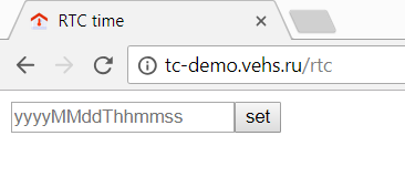
Subsequently, this service is used in a prettier interface:

Application Software
Finally came to what the system was created for. Namely - to the implementation of the applied task.
Any application program should receive the original data, process them and produce the result. Also, perhaps, the system should report the current state.
Baseline data for a warm floor controller are:
- Sensor data - the system is not tied to specific sensors. For each sensor, a unique identifier is generated. For radio sensors, their identifier is padded to 16 bits with zeros, for 1Wire sensors, based on their internal identifier, CRC16 is calculated and used as a sensor identifier. Thus, all sensors have identifiers with a length of 2 bytes.
- Data on heating zones - the number of zones is not fixed, the maximum number is limited by the used relay module. Given this limitation, the WEB interface was also developed.
- Target temperature and schedule - I tried to make the most flexible settings, you can create several heating schemes and you can even assign your own settings to each zone.
Thus, there are a number of settings that need to be somehow set, and there are a number of parameters that the system reports as the current state.
To communicate the controller with the outside world, I implemented a command interpreter that allowed the controller to be managed as well as to receive state data. Commands are transmitted to the controller in human-readable form, and can be transmitted via a UART or WEB socket (if you wish, you can implement support for other protocols, for example telnet).
The command line starts with a '#' and ends with a null character or a newline character. All commands consist of a command name and an operand, separated by a colon. For some commands, the operand is optional, in which case the colon and operand are not specified. Commands in the line are separated by commas. For example:
#ZonesInfo:1,SensorsInfo
And of course, the list of commands starts with the Help command, which lists all valid commands (the commands transmitted for convenience of perception begin with the sign '>' instead of '#'):
>help Help SetZonesCount Zone SetName SetSensor ... LoadCfg SaveCfg #Cmd:Help,CmdRes:Ok
A feature of the implementation of the command interpreter is that information about the result of the command is issued also in the form of a command or a set of commands:
>help … #Cmd:Help,CmdRes:Ok >zone:123 #Cmd:Zone,Value:123,CmdRes:Error,Error:Zone 123 not in range 1-5 >SchemasInfo #SchemasCount:2 #Schema:1,Name:,DOWs:0b0000000 #Schema:2,Name:,DOWs:0b0000000 #Cmd:SchemasInfo,CmdRes:Ok
On the side of the WEB client, a command interpreter is also implemented, which takes these commands and converts them into a graphic form. For example:
>zonesInfo:3 #Zone:3,Name:,Sensor:0x5680,Schema:1,DeltaT:-20 #Cmd:ZonesInfo,CmdRes:Ok
The WEB interface transmitted a request to the controller about zone number 3, and received in response the name of the zone, the identifier of the sensor associated with the zone, the identifier of the circuit assigned to the zone, and the temperature correction for the zone. The command interpreter does not understand fractional numbers, therefore the temperature is transmitted in tenths of a degree, i.e. 12.3 degrees is 123 tenths.
The key feature is that on any command, regardless of the command input method, the controller responds to all clients at once. This allows you to display the state change at once in all sessions of the WEB interface. Since The main transport of the exchange between the controller and the WEB interface is WEB sockets, the controller can transfer data without a request, for example, when new data comes from the sensors:
#sensor:0x5A20,type:w433th,battery:1,button_tx:0,channel:0,temperature:228,humidity:34,uptime_label:130308243,time_label:20180521T235126
Or, for example, that these zones need to be updated:
#Zone:2,TargetTemp:220,CurrentTemp:228,Error:Ok
The controller's WEB interface is built on the use of text commands. On one of the tabs of the interface there is a terminal with which you can enter commands in text form. Also, for debugging purposes, this tab allows you to find out which commands the WEB interface sends and receives during various user actions.
The command interpreter allows you to easily change and increase the functionality of the device, by changing the existing commands and adding new ones. At the same time, debugging of such a system is greatly simplified, since communication with the controller takes place exclusively in human readable language.
Conclusion
Using a similar approach, namely:
- Separation of software on the operating system and application program
- Implementing operating system settings as minimalistic HTTP services
- Separation of system logic from data presentation
- Using human readable communication protocols
allows you to create solutions that are understandable to both users and developers. Such solutions are easy to modify. On the basis of such decisions it is easy to build new devices, with a completely different logic, but which will work on the same principles. You can create a line of devices with the same type of interface:
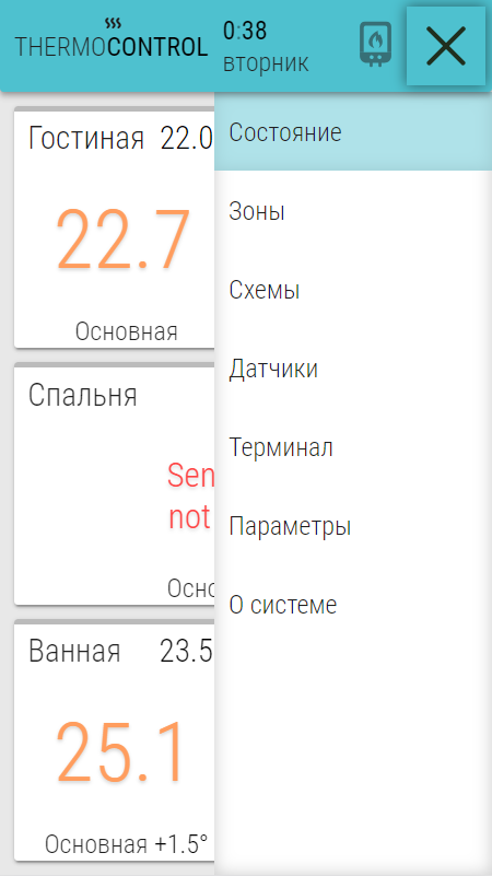
As you can see, in this project, only the first three pages of the interface are directly related to the application, and the rest are almost universal.
In this publication, I describe only my view on the construction of smart devices, and in no case do I pretend to be the ultimate truth.
Who is interested in this topic - write, maybe I'm in something wrong, and maybe some details it makes sense to describe in more detail.
What happened in the end:
Fiasco. The story of one homemade IoT