Firefly-RK3288 Reload
Selecting a development board for the experiments, the choice fell on a rather heaped model from the Chinese manufacturer T-Chip. They sell products under the brand Firefly. They specialize in RockChip chipboard systems. RK3288 is the most productive 32-bit solution from this Chinese company. SoC from RockChip and Allwinner favorably differ from Broadcom chips in RaspberryPi not only with the best characteristics, but also with the production technology - 28nm against 40nm. But of course, in this case, the Chinese are more expensive. I didn’t choose the even cooler 64-bit system RK3399, including because there is reason to believe that it is already significantly hotter. While RK3288 under load is not very hot, even without using any radiators.
Product page . The main hardware parameters of the device: 4 core ARM Cortex-A17 1.8 GHz (some sources insist that there is a Cortex-A12 or A15, but this is not particularly important), 2 GB DDR3 dual-channel, 16 GB eMMC drive, gigabit Ethernet.
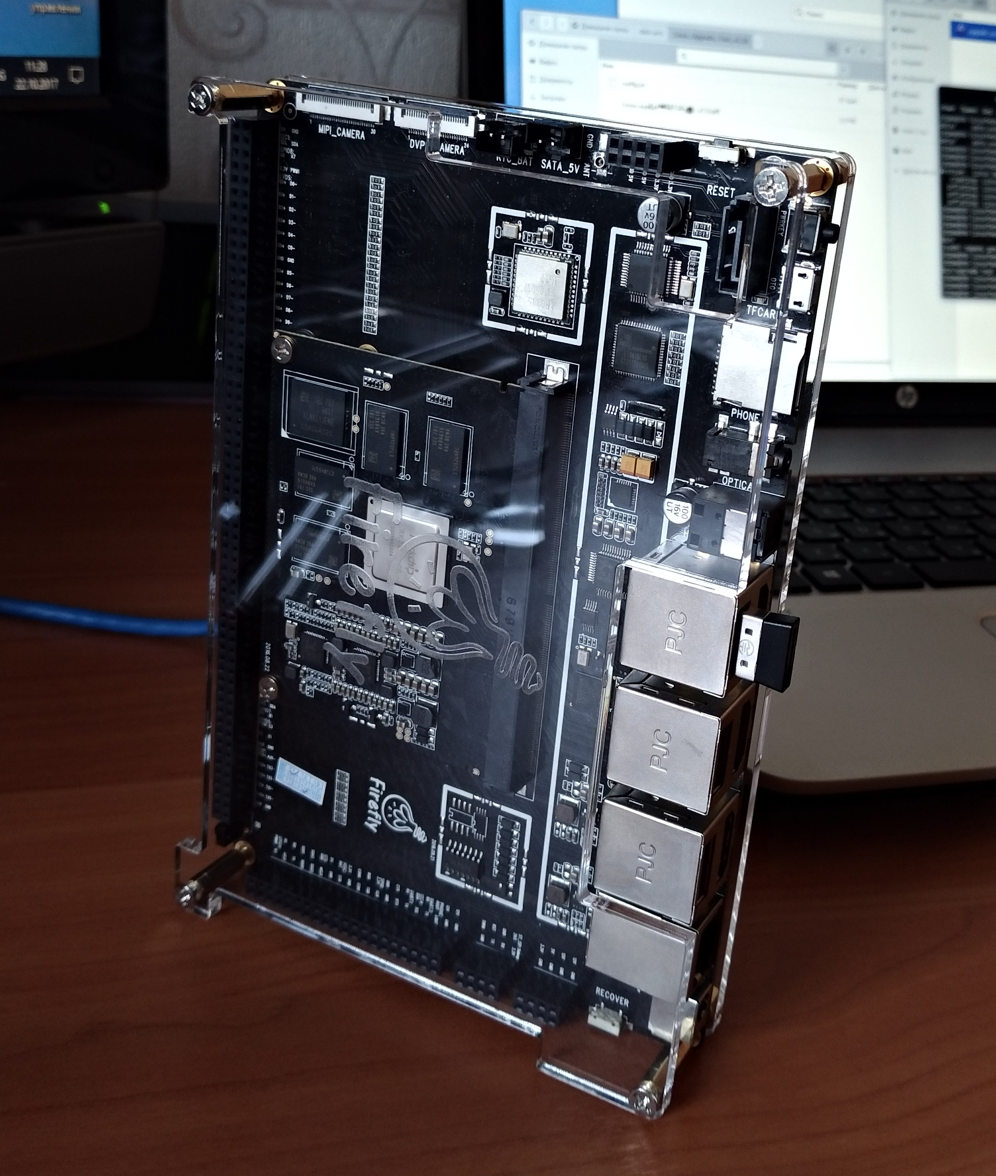
I bought on Ebay, it turned out to be almost the only place where these boards can be ordered to Russia. Internet shop of the most Chinese Firefly does not send to Russia. Do not send to Russia and Indiegogo. What is funny, in the list of countries to send, these strange people allegedly have even now non-existing states :). The seller with Ebay sent a board in a good configuration - a board, a power supply unit (12V 1.5A is needed, sent as it should be with a margin of 2A), a scarf with an antenna, acrylic panels of the case with fasteners. The adapter is true for an American outlet, but everyone should have a hiking adapter :).
Like the CubieBoard boards from CubieTech, which are better known in the Russian market, Firefly provides good informational support. OS images, pinout scheme, etc. are provided. Worthy of praise is the Ubuntu 14 firmware for Firefly. Stable, low memory consumption. Graphic desktop - LXDE. Drawing the interface does not seem ideally fast, but quite decent. By the way, a useful link on how to take screenshots in LXDE:
Lxde wiki . Other useful information is how to set the time:
using dpkg-reconfigure tzdata . Yes, you never guess what, in any Linux shell, is done in a non-trivial way.
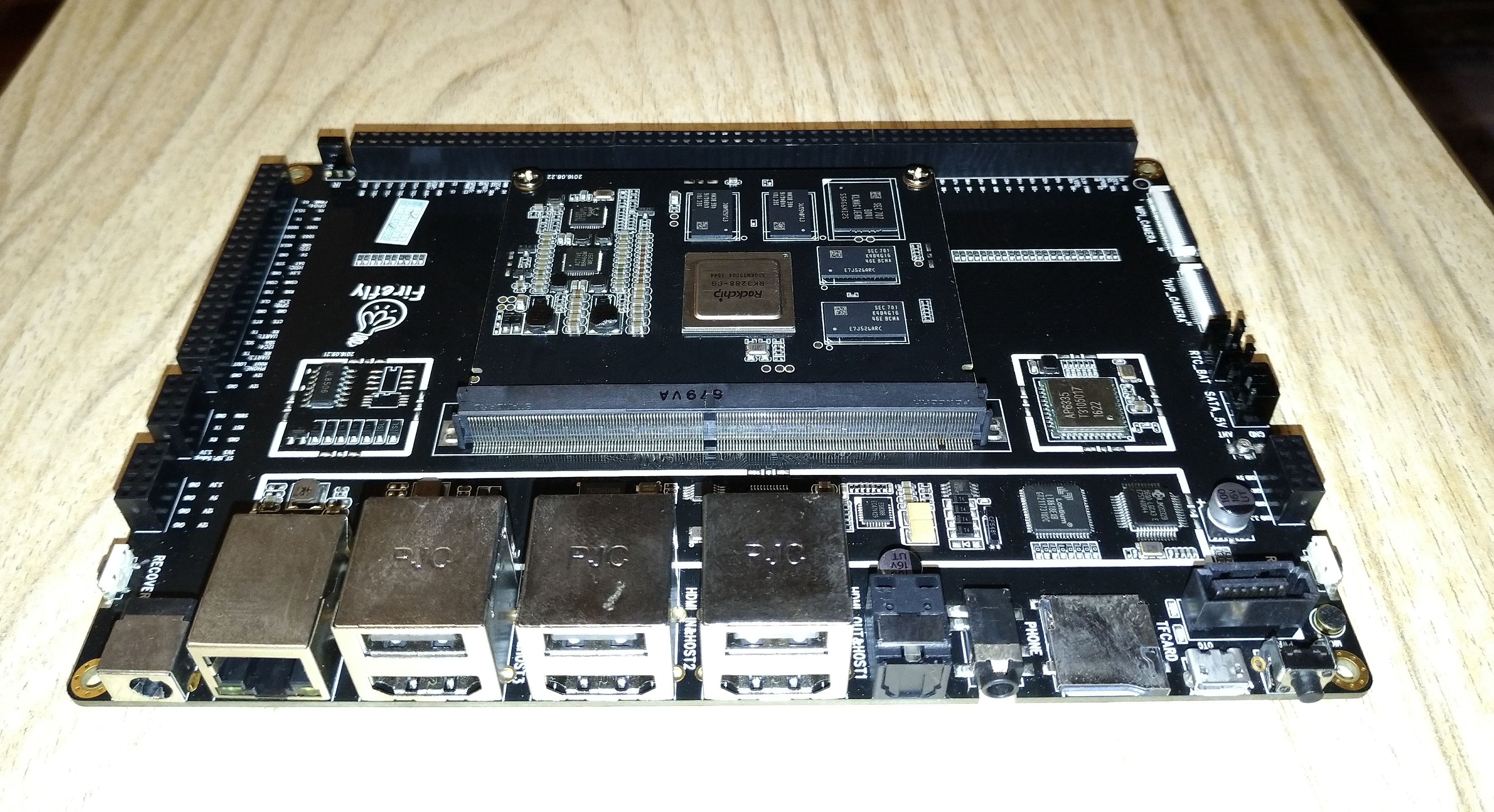
The board has a sandwich structure (sandwich style). The core board contains a SoC RockChip, RAM and a Samsung drive, Realtek Ethernet, as well as a power management and monitoring chip from Active. The main board contains everything else: the Lontium HDMI output controller (two outputs in total), Toshiba HDMI input, JMicron USB-SATA bridge, Ampak chip for wireless interfaces. Connect the two parts through a relatively standard slot MXM3.0 (mobile module PCI Express). The board has many interfaces, as well as four main blocks of pins, a total of 184 pins. Moreover, the manufacturer did not stint on the mother connectors, so surely safer, given that even a few 12V power lines are divorced.
Boot-mode and firmware
The first thing to do with the boards is to flash them. For episodic interaction with developer boards, IoT and all that, it is more convenient to have a Linux system on a computer. I traditionally have it with Linux Fedora 64bit, for all of the 26th version. Official instructions on how to transfer the card to boot-mode and OS firmware:
Flash Image .
Since the
RockChip upgrade_tool fill utility needs to install dependencies . And not every version of the Linux distribution on the host PC says which ones.
I want to share my action algorithm for successfully transferring the board to the boot and uploading the OS image:
1. . 2. ( micro USB - USB). 3. : - RECOVER - RESET - RECOVER 4. - Linux Upgrade Tool ( ): - [user@nb-linuxfedora data-arm]$ unzip Linux_Upgrade_Tool_v1.24.zip - [user@nb-linuxfedora data-arm]$ cd Linux_Upgrade_Tool_v1.24/ - [user@nb-linuxfedora Linux_Upgrade_Tool_v1.24]$ sudo mv upgrade_tool /usr/local/bin/ - [user@nb-linuxfedora Linux_Upgrade_Tool_v1.24]$ sudo chown root:root /usr/local/bin/upgrade_tool - [user@nb-linuxfedora Linux_Upgrade_Tool_v1.24]$ cd /usr/local/bin/ - [user@nb-linuxfedora bin]$ - , upgrade_tool 5. Linux Upgrade Tool <update>.img ( ): [user@nb-linuxfedora bin]
Using
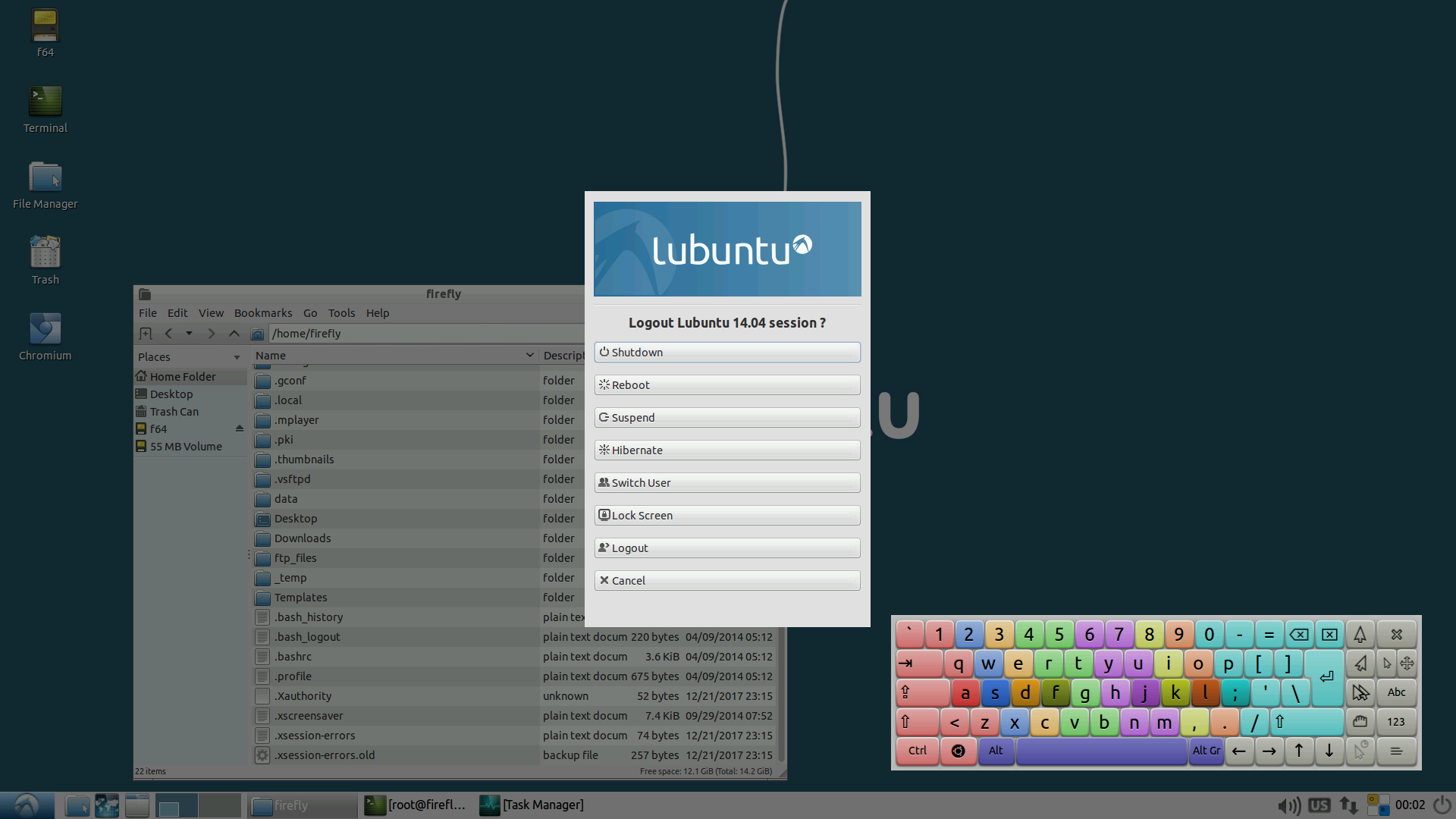
After a successful Firefly-RK3288 Reload firmware, disconnect the USB cable. And you can connect a monitor, keyboard, mouse. And install the g ++ compiler by itself. Ubuntu LXDE for Firefly has a good, minimally sufficient, set of software. Of course, the most useful in this situation is the terminal. There is also a simple system monitor, Leafpad text editor, on-screen keyboard, file manager, media player, Chromium browser and more.
A couple of screenshots:
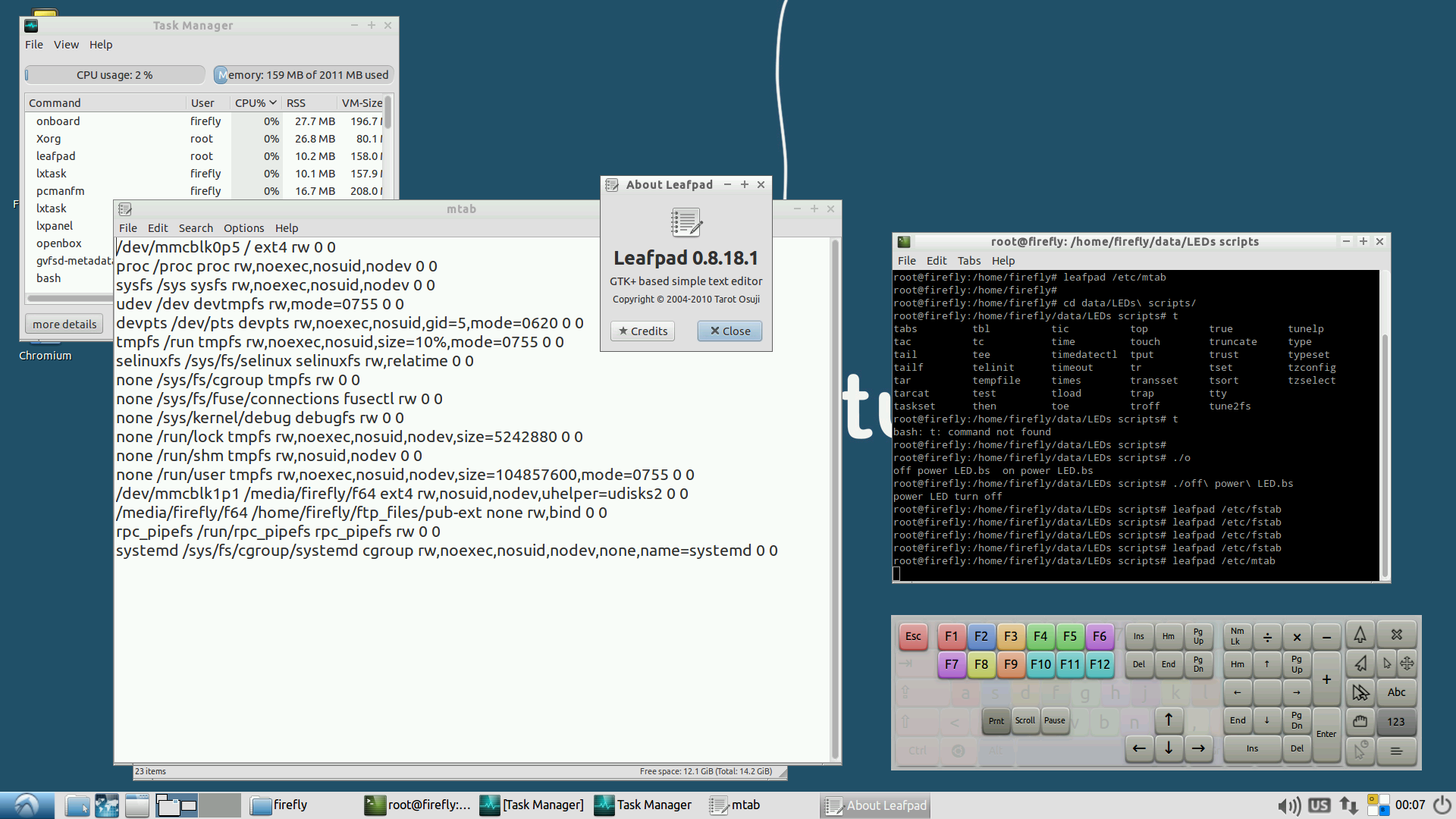
Terminal and Leafpad
Version Information
Of course could not do without a spoon of tar. The board works internally with the resolution of the Full HD image, and the screenshots are saved in the same resolution. But the HDMI-out on the monitor is fed a picture in the resolution only HD ready. Therefore, the image, of course, is not clear enough. But for experiments such picture will fit.
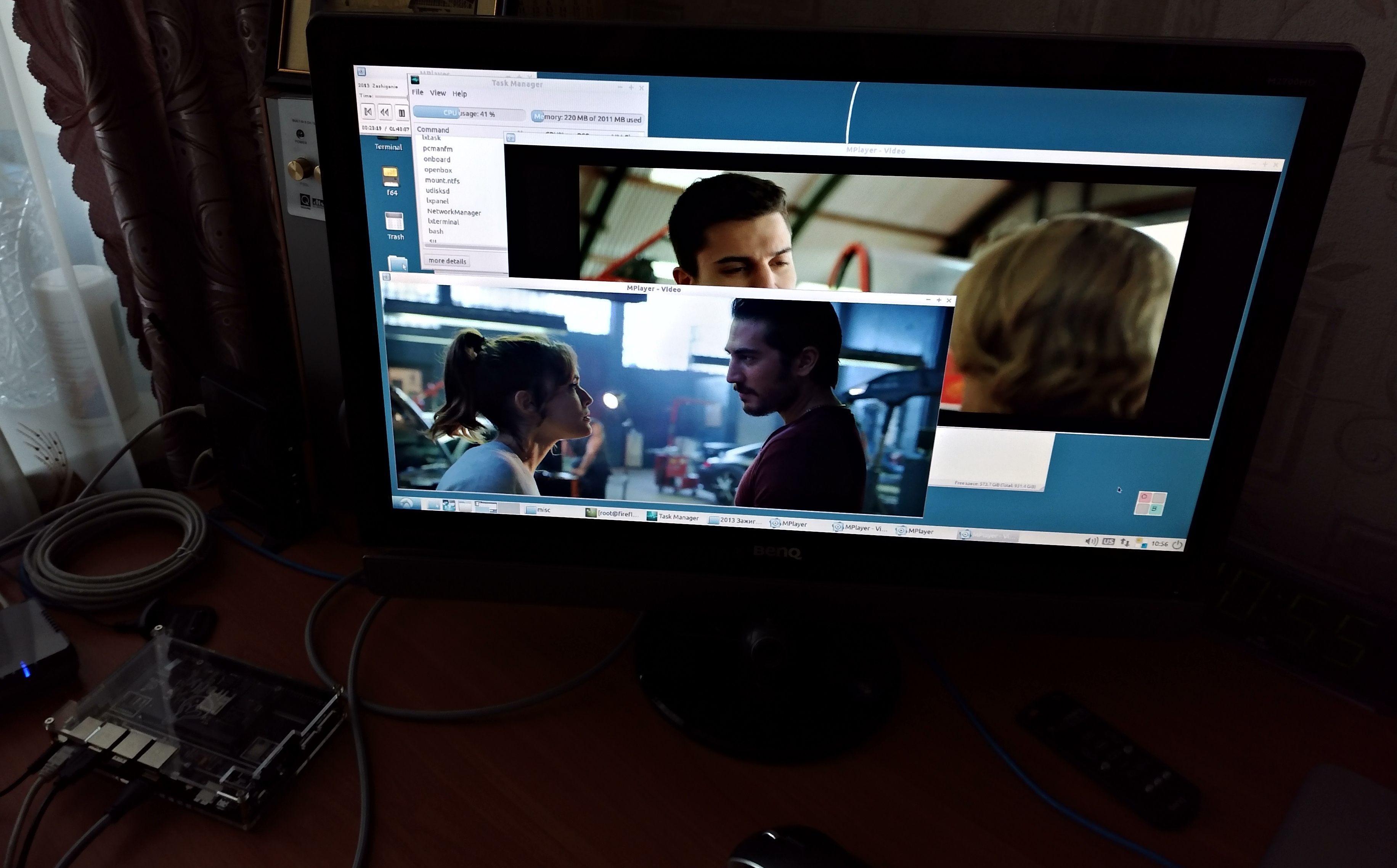
A couple of movies in high quality is not a problem for RK3288, the CPU load is about 50%.
Using I2C-periphery and GPIO-pins
Perhaps one of the most valuable features of such cards is the connection of peripheral devices via the I2C bus, the use of GPIO and other interfaces. Firefly RK3288 Reload has four I2C tires, even five, but the zero bus is used for internal needs of the board, and four others - from 1 to 4 are divorced for use by the user.
The network has enough general information about using the I2C interface. To interact with I2C devices via the terminal, I recommend this article:
“I2C on Cubieboard with Lubuntu” , they use “cube” there, but this is not essential.
And for connecting to I2C peripherals programmatically using file virtualization of I2C buses, we can recommend this:
“Interfacing with I2C Devices” .
As a peripheral device I2C used Microchip temperature sensor - MCP9808. On the manufacturer's website is easy to find a good specification of the device. It is one of the highest quality and most expensive sensors on the market, significantly faster and more accurate than the LM sensors from TI and NXP series.
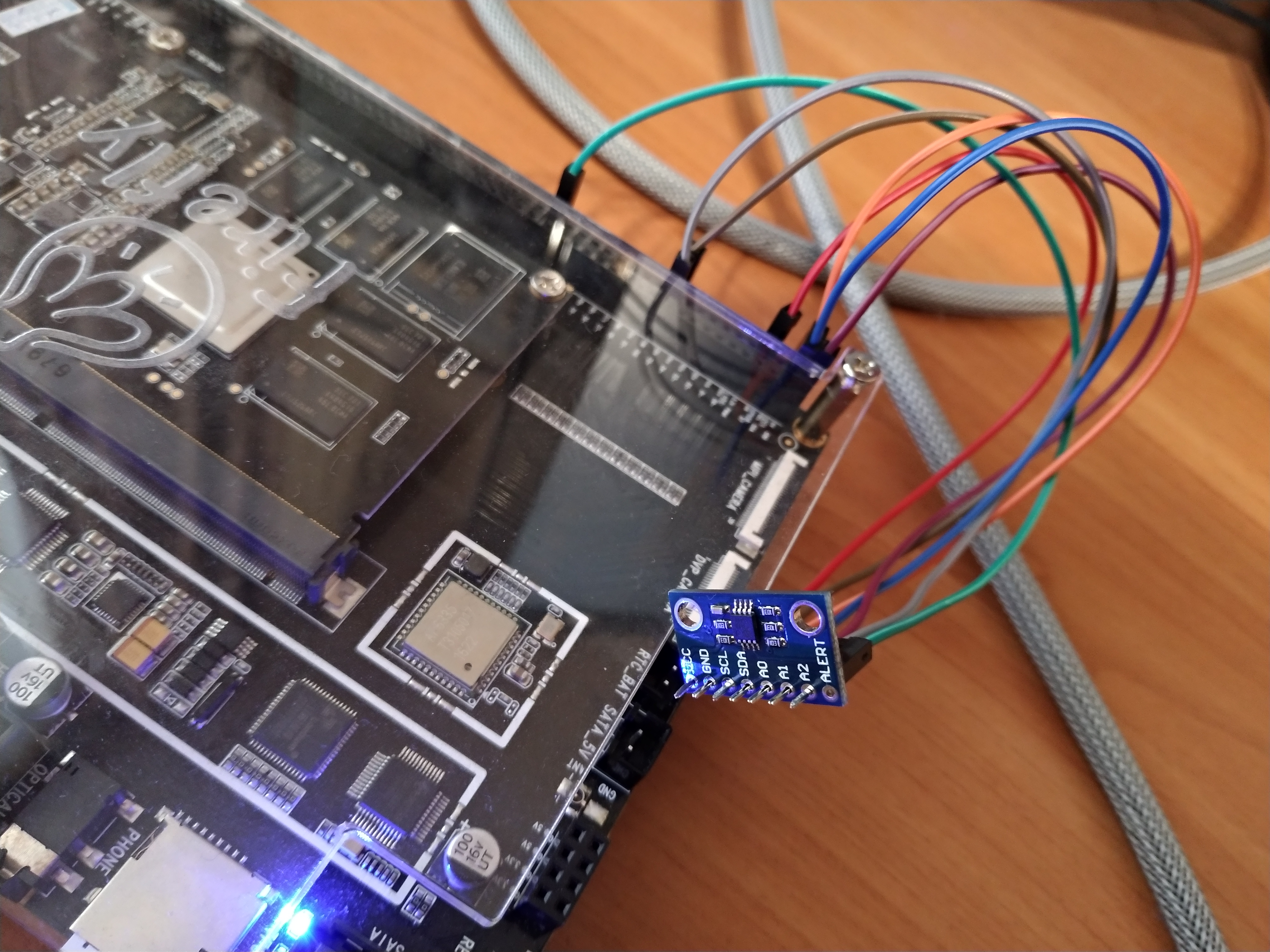
I used this sensor already soldered to a mini CJMCU-9808 card. Also, everything with Ebay - and sensors, and Dupont wiring - to do without soldering. The connection is quite simple: VCC - to 3.3V power supply, GND - to ground, SCL and SDA actually implement the I2C bus (clocking and data lines, respectively), A0 A1 A2 pins set part of the 7-bit address of the I2C device, ALERT can not use, but the alarm line will still be involved further. In the photo, the temperature sensor is connected to the I2C 1 bus, all address contacts are pulled to ground, which means a logical 0 in the corresponding address bit, if the address wiring is plugged into 3.3V, then this bit will be logic 1. The base address of the MCP9808 chip is b0011 and further A2 A1 A0. Only seven bits, in this case b0011000, that is, in hex, 0x18.
Thus, the console utility will issue:
root@firefly:/home/firefly
It can be seen that there is something on the I2C bus number 1 with the address 0x18.
Call:
root @ firefly: / home / firefly # i2cget -y 1 0x18 0x05 w
will give, for example: 0xbc01 (which means a temperature of 27.75 C).
Program options i2cget: 1 - bus number; 0x18 - address connected to the device bus; 0x05 - address of the register (in this case, the temperature); w - indicates that the register stores 2 bytes.
Of course, you can use MCP9808 from your own C ++ program more fully. It should be borne in mind that the contents of the temperature register - 0xbc01 - is inverted, that is, it can be represented as 0x01bc. The first byte 0x01 contains three bits of the alarm cause, one sign bit and four high-temperature bits. The second byte 0xbc contains the lower eight bits of the temperature. The contents of the temperature register Microchip encodes the method of additional code (
two's complement format ). The twelfth bit of the two-byte register encodes the character. If it is 0, then the temperature is positive. If the eleventh bit is 1, then the calculated ambient temperature should be added 2 to the power of 7 degrees Celsius - 2 ^ 7 (128 C), if - equals 0, then - nothing needs to be added. Similarly, 1 in the tenth bit will add 2 ^ 6 (64 C). And so on, 1 in the fourth bit will add 2 ^ 0 (1 C). 1 in the third bit will add 2 ^ -1 (0.5 C). 1 in the last - zero bit will add 2 ^ -4 (0.0625 C). If the sign bit (12th) is equal to 1, then the
trouble has come to the house the temperature is negative. And the decryption of the register is somewhat complicated. In accordance with the principles of two's complement format, you must first invert the bits. Then you need to add one to the lowest bit used, since negative values are encoded not with 0, but with -1. When configuring the default temperature sensor, maximum accuracy is used - up to 0.0625 C. In this case, add one to the last bit, which is responsible for 0.0625 C. That is, you can simply add 1 to the value of the temperature register. If, for example, to increase the speed, reduce the temperature measurement accuracy using the configuration register. Then, at a negative temperature, it will be necessary to add one to the higher bit or to add the number corresponding to this bit. Then it is necessary to convert the bits to the temperature value as in the positive case.
GPIO and ALARM line
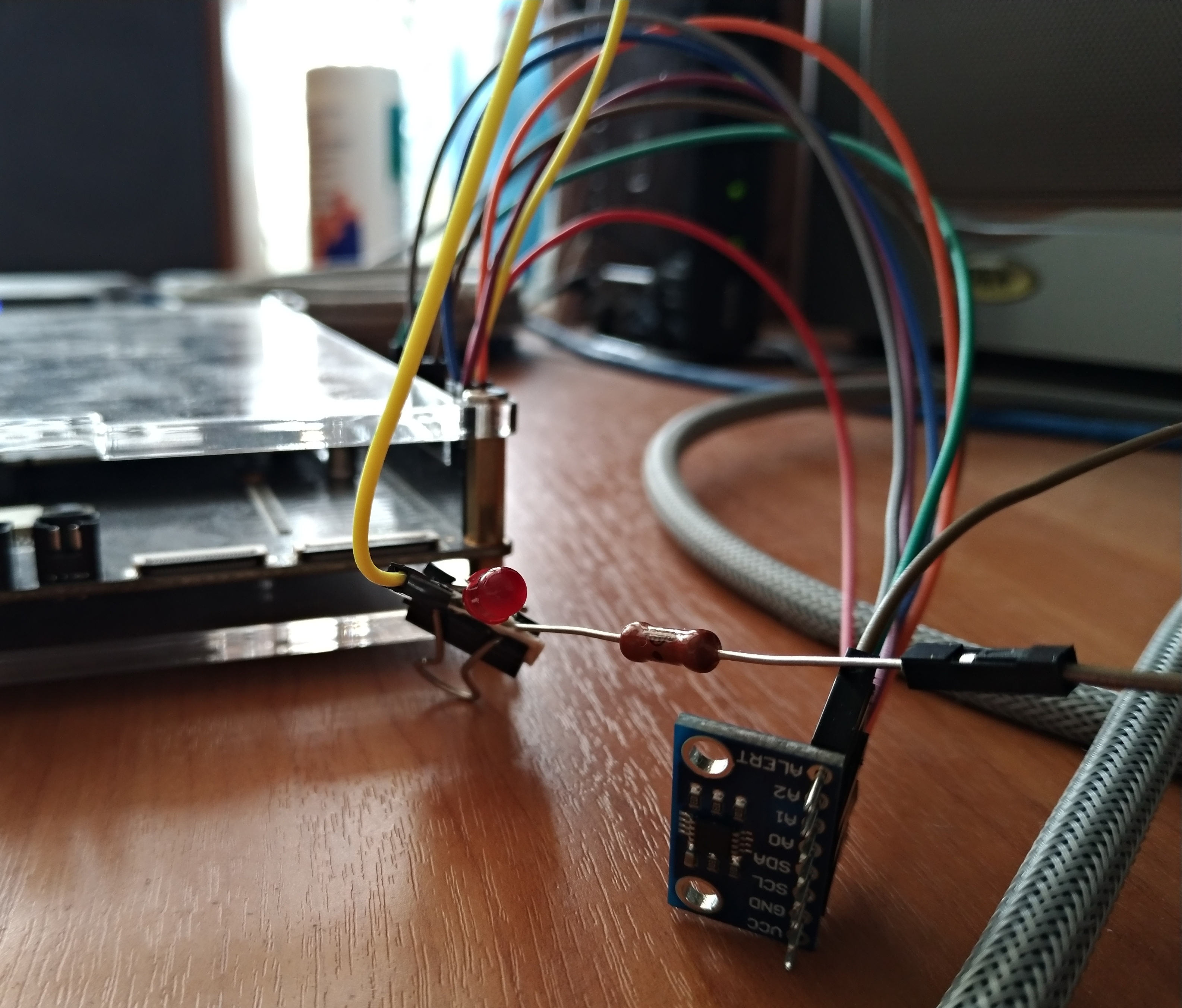
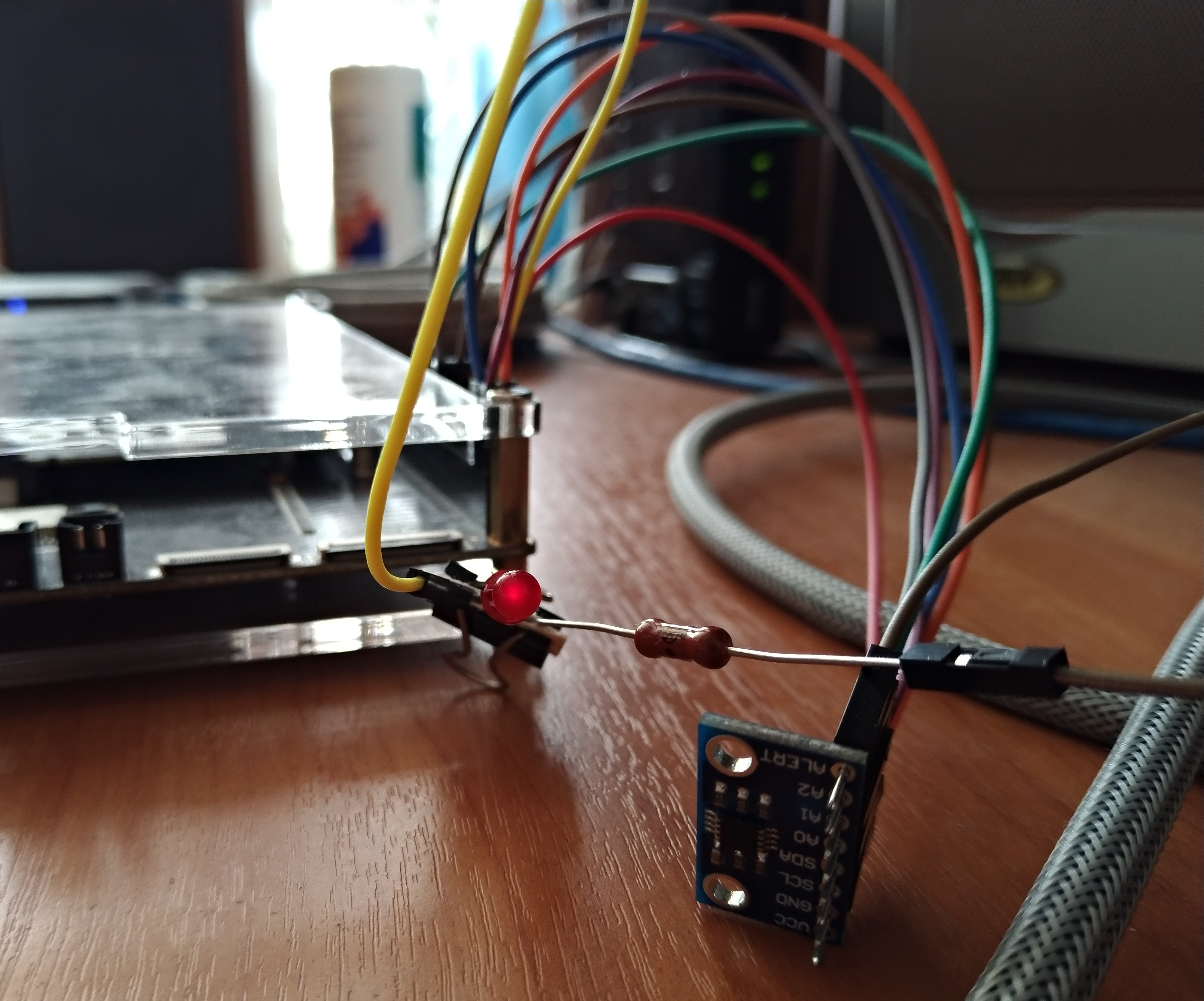
You can use the ALARM line sensor. Including using one of the GPIO lines of Firefly. In the photo of course tin and waste with archaic LEDs and resistance, but the principle itself is important here. How to use GPIO is well described in another article on Habré:
Linux: buttons, LEDs and GPIO . But as it is correctly noted, it is difficult to determine which Gpio number to export for further use. In order to see which lines of Gpio are occupied and which are not, you can use the command:
root@firefly:/home/firefly
Team
firefly@firefly:~$ dmesg
also shows information about Gpio.
The study showed that it is possible to export, for example, a GPIO pin with the number 262. Which is indicated on the board and in the specification as GPIO8 A6. Since in this board, as usual, GPIO blocks contain 32 elements each. It can be assumed that, perhaps, the magic formula is as follows: 32 * block number GPIO + number from postfix. So, we can just get 32 * 8 + 6 = 262. Now, when we start the program, we supply 3.3V power to this Gpio 262 line, and when we leave it, we can stop doing this.
The specification for MCP9808 indicates that the ALARM line on it is open drain, i.e. open drain. This means that when an alarm occurs, this line is closed to the ground, otherwise it is not closed. It also emphasizes the need to use a resistor. In practice, it has been verified that this is really necessary, otherwise, when current flows, the inside of the sensor will heat up to high temperatures. The photo shows the following diagram: GPIO is connected in series to the LED, resistance, open drain (ALARM) of the sensor. It remains to use the configuration register MCP9808 in order to set the permissible temperature limits. When going beyond which an alarm will occur. You can set two levels of too high temperature and one level too low. In general, to work with this digital sensor, of course, you need to carefully read the specification, switch to configuration mode, return to operation mode, and so on. Thus, when the temperature exceeds the set limits, the current will pass through the ALARM contact and light up the LED.
Finally
I would like to mention a useful trick to control the glow of LEDs built into the boards for development. The manuals for Cubieboard 6 show how to turn on the LED1 LED:
$echo default-on > /sys/class/leds/led1-GPIOB9/trigger
And how to turn off LED1:
$echo none > /sys/class/leds/led1-GPIOB9/trigger
Based on this, it was found out how to control the LEDs in the Firefly 3288 Reload.
Turning on a custom yellow LED (actually blue LED):
root@firefly:/home/firefly
Turning off this LED:
root@firefly:/home/firefly
Precautions
When developing for development boards it is important to exercise caution. Coding, of course, happens on a PC, with great desire and cross-compilation too. Then the sources are compiled on a specific target or the ready-made executable file is transferred to the board. And if specialized boards are largely made for the use of various interfaces. Yes, and they are usually not very expensive. It is not recommended to use I2C buses on the expensive PCs themselves, GPIO lines and the like. This can lead to unpleasant computer crashes. At least the console utilities like i2cget clearly warn about this, citing as an example some models of affected laptops.