Do not fit. Kill! (with)
The average literacy of the population in the field of electronics and electrical engineering leaves much to be desired. Maximum solder shemku, and how it works - a dark forest. Unfortunately, all Russian-language textbooks are full of formulas and integrals, from them any person will pull into a dream. In the English literature, things are somewhat better. There are some rather interesting publications, but the English language is the stumbling block here. I will try to explain the basic concepts of electrical engineering as accessible as possible, in a free style, not from an engineer-engineer, but from person to person. A knowledgeable reader may also find some interesting points.
Electricity
The ways of electric current are inscrutable. (c) thoughts from the Internet
Not really. Everything can be described one way or another with the help of a mathematical model, modeling, and even having figured it out quickly on a piece of paper, and some unique people do it in their heads. Who is more convenient. In fact, the epigraph of this chapter was born from ignorance of what electric current is.
Electric current is characterized by several parameters. Voltage U and current I. Of course, we all remember the definitions in physics, but few understand their meanings. I'll start with the voltage. The potential difference or work to move the charge, as dry and uninteresting write in textbooks. In fact, voltage is always measured between two points. It characterizes the ability to create an electric current between these two points. Let's call these points a voltage source. The higher the voltage, the greater the current. Less voltage - less current. But more on that later.
What is current? Imagine an analogy: a riverbed is wires; an electric current is the speed of a stream of water in a river. Then the voltage here is the height difference between the starting point of the river and the end point. Or the voltage is a pump that drives the water if the river flows in the same plane. Such analogies in the initial stages are very helpful in understanding what is happening in the electrical circuit. But, in the end, it is better to abandon them. It is better to present the current as a certain flow of electrons. Amount of charge moved per unit of time. Of course, the textbooks say that de electrons move at a speed of several centimeters per minute and only the electromagnetic field is important, but for now let's forget about it. So, by current one can understand the movement of electric current, i.e. charge. Charge carriers, electrons, are negatively charged and move from negative potential to positive, electric current has the direction from positive potential to negative, from plus to minus, so it is accepted for convenience and so we will use further, forgetting about the electron charge.
Of course, the current itself will not appear, you need to create a voltage between two points and you need some kind of load for the current to flow through it, connected to these two points. It is very useful to know the property that two conductors are needed for current flow: direct, to load, and reverse, from load to source. For example, if the conductors of the voltage source are not closed, there will be no current.
What is a voltage source? Imagine it as a black box with at least two outputs for connection. The simplest examples from real life: electrical outlet, battery, battery, etc.
The ideal voltage source has a constant voltage when any current flows through it. What happens if you close the clips of the ideal voltage source? An infinitely large current will flow. In reality, voltage sources can not give an infinitely large current, because they have some resistance. For example, the wires in the 220V power socket from the outlet itself to the substation have resistance, albeit small, but rather tangible. Wires from substations to power plants also have resistance. We must not forget about the impedance of transformers and generators. Batteries have an internal resistance due to an internal chemical reaction, which has a finite flow rate.
What is resistance? In general, this topic is quite extensive. Perhaps I will describe in one of the following chapters. In short, this is the parameter that binds the current and voltage. It characterizes what current will flow at an applied voltage to this resistance. If we speak of the “water” analogy, then resistance is a dam on the river’s path. The smaller the hole in the dam - the greater the resistance. This relationship describes Ohm’s law:
. As the saying goes: "You do not know Ohm's law, stay at home!".
Knowing Ohm's law, not sitting at home, having any current source with a given voltage and resistance in the form of a load, we can very accurately predict which current will flow.
Real voltage sources have some kind of internal voltage and give some final current, called short circuit current. At the same time, batteries and accumulators are also discharged with time and have nonlinear internal resistance. But for now, let's also forget about it, and here's why. In real-world circuits, it is more convenient to analyze using instantaneous instantaneous values of voltage and current, so we will consider voltage sources ideal. Except for the fact that it is necessary to calculate the maximum current that a source is capable of giving.
About the "water" analogy of electric current. As I already wrote, it is not very true, since the speed of the river to the dam and after the dam will be different, the amount of water before and after the dam will also be different. In real-world circuits, the electric current flowing into the resistor and resulting from it will be equal to each other. The current through the direct wire to the load, and the return wire from the load to the source, is also equal to each other. The current does not come from anywhere and does not disappear anywhere, as much as “flowed” into the circuit node, and so much will “flow out”, even if there are several paths. For example, if there are two paths of current flow from a source, then it will flow along these paths, with the total current of the source being equal to the sum of two currents. And so on. This is an illustration of Kirchhoff's law. It is very simple.
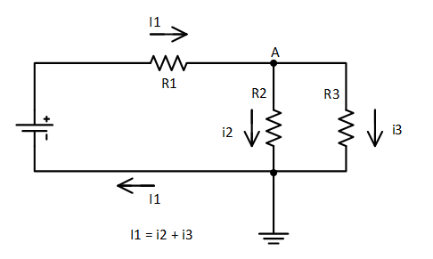
There are also two more important rules. With parallel connection of elements, the voltage in each of the elements is the same. For example, the voltage across the resistor R2 and R3, in the figure above, is the same, but the currents can be different if the resistors have different resistances, according to Ohm's law. The current through the battery is equal to the current on the resistor R1 and is equal to the sum of the currents on the resistors R2 and R3. With a serial connection of the voltage elements are added. For example, the voltage that the battery produces, i.e. its EMF is equal to the voltage across the resistor R1 + voltage across the resistor R2 or R3.
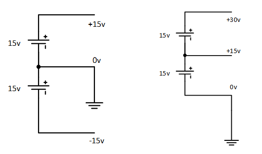
As I already wrote, the voltage is always measured between two points. Sometimes, in the literature you can find: "The voltage at the point of such and such." This means the voltage between this point and the point of zero potential. Create a point of zero potential can, for example, grounded circuit. Usually, the “ground” circuit in the place of the very negative potential near the power supply, for example, as in the figure above. However, this is not always the case, and the use of zero is fairly arbitrary, for example, if we need bipolar power +15 and -15 volts, then we need to "land" no longer -15v, but the potential is in the middle. If we ground -15v, then we get 0, +15, + 30c. See pictures below.
Grounding is also used as a protective or working. Protective grounding is called zeroing. If the isolation of the circuit in any other area other than the ground is broken, then a large current will flow through the zero wire and a protection will be triggered which will disconnect part of the circuit. We must provide protection in advance by placing a circuit breaker or other device in the path of current flow.
Sometimes the "land" scheme is impossible or impossible. Instead of land, the term common point or zero is used. The voltages in such circuits are indicated relative to the common point. Moreover, the whole scheme is relative to the earth, zero potential can be located anywhere. See drawing.
Usually, Xv is close to 0 volts. On the one hand, such ungrounded circuits are safer, since if a person touches the circuit and the earth at the same time, the current will not flow, because There is no return path for current flow. Those. the circuit will be grounded through the person. But on the other hand such schemes are tricky. If the isolation of the circuit from the earth at any point of it is broken, we will not know it. What could be dangerous at high voltages Xv.
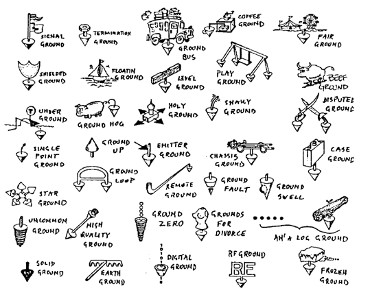
In general, land is a rather broad and vague term. There are a lot of terms and names of the earth, depending on where the circuit is “grounded”. Under the ground can be understood as a protective earth, and the working earth (by the flow of current through it during normal operation), as a signal ground, and power ground (by current), both analog ground, and digital ground (by signal) . Under the ground can be understood as a common point or vice versa, a common point is understood as the earth or and be it. Also in the scheme can be present all the land at the same time. So you need to look at the context. There is even such a funny picture in foreign literature, see below. But usually the ground is a circuit of 0 volts and this is the point from which the potential of the circuit is measured.
Until now, referring to the voltage source, I did not touch the kind of this voltage itself. Voltage is changing with time and is not changing. Those. variable and constant. For example, the voltage varying according to the sinusoidal law is well known to everyone, this voltage is 220V in household outlets. It is very easy to work with constant voltage, we have already done it above, when we considered the Kirchhoff law. And what to do with alternating voltage and how to treat it?
The figure shows several periods of alternating voltage 220v 50Hz (blue line). The red line is a constant voltage of 220V, for comparison.
We’ll decide first about what a 220v voltage is, by the way, according to a new standard, it’s supposed to count 230v. This is the actual value of the voltage. The amplitude value will be at the root of 2 times higher and will be approximately 308v. The effective value is the value of the voltage at which the same heat is generated in a conductor over a period of alternating current as at a constant current of the same voltage. In mathematical terms, this is the rms value of the voltage. In the English literature, the term RMS is used, and devices that measure the true effective value are marked with “true RMS”.
At first glance, this may seem inconvenient, some actual value, but this is convenient for calculating power without the need for voltage conversion.
AC voltage is still conveniently regarded as a constant voltage taken at any point in time. After that, analyze the circuit several times, changing the sign of the constant voltage to reverse. First consider the operation of the circuit with a constant positive voltage, then change the sign from positive to negative.
For AC voltage, you also need two wires. They are called phase and zero. Sometimes zero ground. Such a system is called single phase. Phase voltage is measured relative to zero and varies with time, as shown in the figure above. With a positive voltage half-wave, the current flows from the phase to the resistive load and returns from the load through the neutral wire. With a negative half-wave, the current flows through the zero wire and returns over the phase.
The industry is widely used three-phase network. This is a special case of multiphase systems. In fact, everything is the same as the single-phase system, only multiplied by 3, i.e. the use of three phases and three lands simultaneously. It was first invented by N. Tesla, subsequently improved by M. O. Dolivo-Dobrovolsky. The improvement consisted in the fact that for the transfer of three-phase electric current it was possible to throw out extra wires, four is enough: three phases ABC and a neutral wire, or even three phases, abandoning zero. The zero wire is often grounded. The figure below is zero common.
Why are 3 phases, and no more, no less? On the one hand, the 3 phases are guaranteed to create a rotating magnetic field, so necessary for the electric motors to rotate or received from the generators of power plants, on the other hand it is economically advantageous from the material point of view. Less is impossible, and more is not needed.
To guarantee the creation of a rotating field in a three-phase network, it is necessary that the voltage phases are shifted relative to each other. If we take the full period of stress for 360 degrees, then 360/3 = 120 degrees. Those. the voltage of each phase is shifted relative to each other by 120 degrees. See picture below.

Here is a graph of the voltage of a 3-phase network of 380v over time. As can be seen from the figure, everything is the same as with a single-phase network, only the voltage has increased. 380V is the so-called linear voltage of the network Ul, i.e. voltage measured between two phases. The figure shows an example of finding the instantaneous value of Ul. It also varies sinusoidally. Also, along with the linear voltage distinguish phase Uf. It is measured between phase and zero. Phase voltage in this three-phase network is equal to 220V. Under the phase and linear voltage, of course, means the current voltage. Corresponding linear to phase voltage, as the root of three.
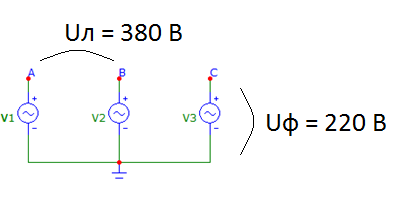
The load to the three-phase network can be connected as you like - to the phase voltage: between a phase and zero, or to a line voltage: between two phases. If the load is connected to the phase voltage, then this connection is called a star. It is shown above. If the linear voltage - the connection is a triangle. If the same load is connected to the line voltages between all three phases, then such networks are symmetrical. The current through the zero wire in symmetric networks does not flow. See fig. below. Industrial networks are also considered conditionally symmetrical. As a rule, zero is present in such networks, but only for defensive purposes. Sometimes it may be absent altogether. Funny picture from the wiki clearly illustrates how current flows in such networks.
This completes the overview of electricity and electricity. Perhaps in the future I will explain on the fingers how the diode and the transistor work, what is a zener diode, a thyristor and other elements. Write about what you are interested in reading.
Bibliographic list
- The Art of Circuit Engineering, P. Horowitz. 2003
- GROUNDS FOR GROUNDING. A Circuit-to-System Handbook, Elya B. Joffe, Kai-Sang Lock.
- Wiki and online resources.