 The article assumes that the reader already has an understanding of the basics of MPLS L3VPN .
Hey. Suppose you are an
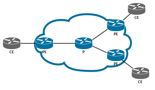
ISP . And like any fairly large ISP, the core of your network is based on IP / MPLS. If you really simplify, then your network can be represented by the scheme shown above. Let's also assume that you, as an ISP, are selling your customers L3VPN service, which is implemented on your network in accordance with RFC 4364 (BGP / MPLS IP VPNs). And if the L3VPN client on a certain site does not have enough directly connected network, and wants to announce additional routes to other sites, then you raise a BGP session between your equipment (PE) and a client equipment (CE), through which the client can announce the desired routes. However, you do not apply any filters / policies to this session, guided by the fact that this is a VPN client, and he is free to “chase” everything he wants (within the limit on the number of prefixes, for example). And now attention, a question: what will happen if during this BGP session a client announces routes (routes) to you (provider), adding Route Target Community to them? This may be, for example, the result of an error, or the desire to experiment.
Just in case, remember that Route Target is one of the special extended BGP communities used in MPLS L3VPN to select a VRF, the route table of which needs to be set up in MP-BGP route. And since RT is a community, in theory, nothing prevents us from adding it to the usual IPv4 routes.
Let us return to the question of what can happen if CE announces routes marked with RT on PE (there are no BGP policies on PE). A little thought, we can assume that there are 3 different outcomes:
- PE will drop such an announcement.
- PE will remove RT from the announcement, add the RT of the corresponding VRF to it and send an announcement to another PE.
- PE will accept the announcement unchanged, add the RT of the corresponding VRF to it (ie, the announcement will already contain two RT) and send the announcement to another PE.
The most interesting and at the same time dangerous for the service provider, of course, is the last option. In this case, the client would potentially be able to disrupt the routing in other VRFs, both client and internal, technological.
But enough to assume, let's check. For more interest, we will check at once on several Network OS. In Eve-NG, this scheme was assembled:
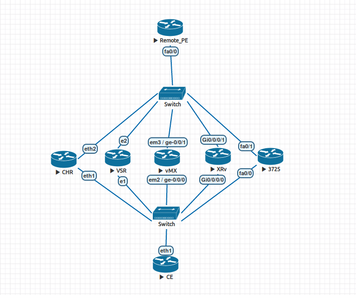
List of test participants:
- CHR - Mikrotik CHR , RouterOS 6.40.8
- VSR - Nokia VSR, TiMOS 15.0.R6
- vMX - Juniper vMX, JUNOS 14.1R1.10
- XRv - Cisco XRv, IOS-XR 6.1.1
- 3725 - Cisco 3725 (Dynamips), IOS 12.4
Auxiliary routers:
- Remote PE - Cisco 3725 (Dynamips), IOS 12.4
- CE - Mikrotik CHR, RouterOS 6.40.8
Description of the scheme:
- "Participants of testing" - PE routers. VRF-100 (RT 65001: 100) is created on each of them, within this VRF-100 a BGP session with CE is organized without any filters / policies.
- Each of the tested PEs has an MP-BGP session with a Remote_PE router, which routes VRFs.
- The CE router has 5 subinterfaces (1 to each PE), in each subinterface a BGP session is raised to the corresponding CE. Each PE is announced with a prefix of the form 1.1.1. N / 32, where N is the sequence number of PE from left to right. Using the export policy from CE, each of these prefixes is added to the community RT: 65001: 200.
- Two VRFs are created on Remote_PE: VRF-100 (RT 65001: 100) and VRF-200 (RT 65001: 200)
- MPLS-transport, P-routers, RR and other joys, usually present in the real network, are omitted here, because it doesn't matter to us here.
For those who are not satisfied with the description “only in words,” I will give the configs of all the devices involved.
CE/interface vlan add interface=ether1 name=ether1.10 vlan-id=10 add interface=ether1 name=ether1.20 vlan-id=20 add interface=ether1 name=ether1.30 vlan-id=30 add interface=ether1 name=ether1.40 vlan-id=40 add interface=ether1 name=ether1.50 vlan-id=50 /interface wireless security-profiles set [ find default=yes ] supplicant-identity=MikroTik /routing bgp instance set default as=65002 /ip address add address=192.168.30.2/24 interface=ether1.30 network=192.168.30.0 add address=192.168.10.2/24 interface=ether1.10 network=192.168.10.0 add address=192.168.20.2/24 interface=ether1.20 network=192.168.20.0 add address=192.168.40.2/24 interface=ether1.40 network=192.168.40.0 add address=192.168.50.2/24 interface=ether1.50 network=192.168.50.0 /ip dhcp-client add disabled=no interface=ether3 add disabled=no interface=ether1.30 /ip route add distance=1 dst-address=1.1.1.1/32 type=blackhole add distance=1 dst-address=1.1.1.2/32 type=blackhole add distance=1 dst-address=1.1.1.3/32 type=blackhole add distance=1 dst-address=1.1.1.4/32 type=blackhole add distance=1 dst-address=1.1.1.5/32 type=blackhole /routing bgp network add network=1.1.1.3/32 add network=1.1.1.1/32 add network=1.1.1.2/32 add network=1.1.1.4/32 add network=1.1.1.5/32 /routing bgp peer add comment=VMX name=VMX out-filter=TO-VMX remote-address=192.168.30.1 \ remote-as=65001 add comment=CHR name=CHR out-filter=TO-CHR remote-address=192.168.10.1 \ remote-as=65001 add comment=VSR name=VSR out-filter=TO-VSR remote-address=192.168.20.1 \ remote-as=65001 add comment=XRV name=XRV out-filter=TO-XRV remote-address=192.168.40.1 \ remote-as=65001 add comment=3725 name=3725 out-filter=TO-3725 remote-address=192.168.50.1 \ remote-as=65001 /routing filter add action=accept chain=TO-VMX prefix=1.1.1.3 set-route-targets=65001:200 add action=accept chain=TO-CHR prefix=1.1.1.1 set-route-targets=65001:200 add action=accept chain=TO-VSR prefix=1.1.1.2 set-route-targets=65001:200 add action=accept chain=TO-XRV prefix=1.1.1.4 set-route-targets=65001:200 add action=accept chain=TO-3725 prefix=1.1.1.5 set-route-targets=65001:200 add action=discard chain=TO-VMX add action=discard chain=TO-CHR add action=discard chain=TO-VSR add action=discard chain=TO-XRV add action=discard chain=TO-3725 /system identity set name=CE
CHR /interface bridge add name=lo0 protocol-mode=none /interface vlan add interface=ether1 name=ether1.10 vlan-id=10 add interface=ether2 name=ether2.10 vlan-id=10 /interface wireless security-profiles set [ find default=yes ] supplicant-identity=MikroTik /routing bgp instance set default as=65001 add as=65001 name=vrf-100 redistribute-other-bgp=yes router-id=192.168.10.1 \ routing-table=VRF-100 /ip address add address=192.168.10.1/24 interface=ether1.10 network=192.168.10.0 add address=10.0.1.1/24 interface=ether2.10 network=10.0.1.0 add address=10.1.1.1 interface=lo0 network=10.1.1.1 /ip dhcp-client add disabled=no interface=ether1 /ip route vrf add export-route-targets=65001:100 import-route-targets=65001:100 interfaces=\ ether1.10 route-distinguisher=65001:100 routing-mark=VRF-100 /routing bgp instance vrf add redistribute-other-bgp=yes routing-mark=VRF-100 /routing bgp peer add address-families=vpnv4 comment=remote_PE name=remote_PE remote-address=\ 10.10.10.10 remote-as=65001 update-source=lo0 add comment=CE instance=vrf-100 name=CE remote-address=192.168.10.2 \ remote-as=65002 /routing ospf network add area=backbone network=10.0.0.0/8 /system identity set name=CHR
VSR # TiMOS-B-15.0.R6 both/x86_64 Nokia 7750 SR Copyright (c) 2000-2017 Nokia. # All rights reserved. All use subject to applicable license agreements. # Built on Mon Nov 20 12:58:19 PST 2017 by builder in /builds/150B/R6/panos/main # Generated MON JAN 01 00:32:55 2018 UTC exit all configure #-------------------------------------------------- echo "System Configuration" #-------------------------------------------------- system snmp shutdown exit time sntp shutdown exit zone UTC exit exit #-------------------------------------------------- echo "System Security Configuration" #-------------------------------------------------- system security dist-cpu-protection policy "_default-access-policy" create exit policy "_default-network-policy" create exit exit exit exit #-------------------------------------------------- echo "Log Configuration" #-------------------------------------------------- log exit #-------------------------------------------------- echo "Card Configuration" #-------------------------------------------------- card 1 card-type iom-v mda 1 mda-type m20-v no shutdown exit no shutdown exit #-------------------------------------------------- echo "Port Configuration" #-------------------------------------------------- port 1/1/1 description "CE" ethernet mode hybrid encap-type qinq exit no shutdown exit port 1/1/2 description "remote_PE" ethernet mode hybrid encap-type qinq exit no shutdown exit port 1/1/3 shutdown ethernet exit exit port 1/1/4 shutdown ethernet exit exit #-------------------------------------------------- echo "Management Router Configuration" #-------------------------------------------------- router management exit #-------------------------------------------------- echo "Router (Network Side) Configuration" #-------------------------------------------------- router Base interface "remote_PE" address 10.0.2.1/24 port 1/1/2:20.* no shutdown exit interface "system" address 10.2.2.2/32 no shutdown exit autonomous-system 65001 #-------------------------------------------------- echo "OSPFv2 Configuration" #-------------------------------------------------- ospf 0 area 0.0.0.0 interface "system" no shutdown exit interface "remote_PE" mtu 1500 no shutdown exit exit no shutdown exit exit #-------------------------------------------------- echo "Service Configuration" #-------------------------------------------------- service customer 1 create description "Default customer" exit vprn 100 customer 1 create autonomous-system 65001 route-distinguisher 65001:100 vrf-target target:65001:100 interface "CE" create address 192.168.20.1/24 sap 1/1/1:20.0 create exit exit bgp group "CE" type external export "TO-CE" peer-as 65002 neighbor 192.168.20.2 exit exit no shutdown exit service-name "VRF-100" no shutdown exit exit #-------------------------------------------------- echo "Router (Service Side) Configuration" #-------------------------------------------------- router Base #-------------------------------------------------- echo "OSPFv2 Configuration" #-------------------------------------------------- ospf 0 no shutdown exit #-------------------------------------------------- echo "Policy Configuration" #-------------------------------------------------- policy-options begin policy-statement "TO-CE" entry 10 action accept exit exit exit commit exit #-------------------------------------------------- echo "BGP Configuration" #-------------------------------------------------- bgp group "remote_PE" family vpn-ipv4 type internal local-address system neighbor 10.0.2.2 exit exit no shutdown exit exit exit all
vMX ## Last commit: 2018-05-25 12:37:27 UTC by root version 14.1R1.10; system { host-name vmx01; root-authentication { encrypted-password "$1$zA/8snt5$g3mYVmz7MzTZZOhtjRX6g1"; ## SECRET-DATA } } interfaces { ge-0/0/0 { vlan-tagging; encapsulation flexible-ethernet-services; unit 30 { vlan-id 30; family inet { address 192.168.30.1/24; } } } ge-0/0/1 { vlan-tagging; encapsulation flexible-ethernet-services; unit 30 { vlan-id 30; family inet { address 10.0.3.1/24; } } } lo0 { unit 0 { family inet { address 10.3.3.3/32; } } } } routing-options { autonomous-system 65001; } protocols { bgp { group remote_PE { type internal; local-address 10.3.3.3; family inet-vpn { unicast; } neighbor 10.10.10.10; } } ospf { area 0.0.0.0 { interface lo0.0; interface ge-0/0/1.30; } } } routing-instances { VRF-100 { instance-type vrf; interface ge-0/0/0.30; route-distinguisher 65001:100; vrf-target target:65001:100; protocols { bgp { group CE { type external; peer-as 65002; neighbor 192.168.30.2; } } } } }
XRv !! IOS XR Configuration 6.1.1 !! Last configuration change at Fri May 25 15:24:01 2018 by Cisco ! hostname XRv vrf VRF-100 address-family ipv4 unicast import route-target 65001:100 ! export route-target 65001:100 ! ! ! interface Loopback0 no shutdown ipv4 address 10.4.4.4 255.255.255.255 ! interface MgmtEth0/0/CPU0/0 no shutdown shutdown ! interface GigabitEthernet0/0/0/0.40 no shutdown vrf VRF-100 ipv4 address 192.168.40.1 255.255.255.0 encapsulation dot1q 40 ! interface GigabitEthernet0/0/0/1.40 no shutdown ipv4 address 10.0.4.1 255.255.255.0 encapsulation dot1q 40 ! interface GigabitEthernet0/0/0/2 no shutdown shutdown ! route-policy TO-CE pass end-policy ! route-policy FROM-CE pass end-policy ! router ospf main area 0 interface Loopback0 ! interface GigabitEthernet0/0/0/1.40 ! ! ! router bgp 65001 address-family ipv4 unicast ! address-family vpnv4 unicast ! neighbor 10.10.10.10 remote-as 65001 update-source Loopback0 address-family vpnv4 unicast ! ! vrf VRF-100 rd 65001:100 bgp router-id 192.168.40.1 address-family ipv4 unicast ! neighbor 192.168.40.2 remote-as 65002 address-family ipv4 unicast route-policy FROM-CE in route-policy TO-CE out ! ! ! ! end
3725 ! version 12.4 service timestamps debug datetime msec service timestamps log datetime msec no service password-encryption ! hostname 3725 ! boot-start-marker boot-end-marker ! ! no aaa new-model memory-size iomem 5 ip cef ! ! ! ! ip vrf VRF-100 rd 65001:100 route-target export 65001:100 route-target import 65001:100 ! no ip domain lookup ! multilink bundle-name authenticated ! ! ! archive log config hidekeys ! ! ! interface Loopback0 ip address 10.5.5.5 255.255.255.255 ! interface FastEthernet0/0 no ip address duplex auto speed auto ! interface FastEthernet0/0.50 encapsulation dot1Q 50 ip vrf forwarding VRF-100 ip address 192.168.50.1 255.255.255.0 ! interface FastEthernet0/1 no ip address duplex auto speed auto ! interface FastEthernet0/1.50 encapsulation dot1Q 50 ip address 10.0.5.1 255.255.255.0 ! router ospf 123 log-adjacency-changes network 10.0.0.0 0.255.255.255 area 0 ! router bgp 65001 no bgp default ipv4-unicast no bgp default route-target filter bgp log-neighbor-changes neighbor 10.10.10.10 remote-as 65001 neighbor 10.10.10.10 update-source Loopback0 ! address-family vpnv4 neighbor 10.10.10.10 activate neighbor 10.10.10.10 send-community extended exit-address-family ! address-family ipv4 vrf VRF-200 no synchronization exit-address-family ! address-family ipv4 vrf VRF-100 neighbor 192.168.50.2 remote-as 65002 neighbor 192.168.50.2 activate neighbor 192.168.50.2 soft-reconfiguration inbound no synchronization exit-address-family ! ip forward-protocol nd ! ! ip http server no ip http secure-server ! ! ! control-plane ! ! ! line con 0 line aux 0 line vty 0 4 ! ! end
Remote_PE ! version 12.4 service timestamps debug datetime msec service timestamps log datetime msec no service password-encryption ! hostname remote_PE ! boot-start-marker boot-end-marker ! ! no aaa new-model memory-size iomem 5 ip cef ! ! ! ! ip vrf VRF-100 rd 65001:100 route-target export 65001:100 route-target import 65001:100 ! ip vrf VRF-200 rd 65001:200 route-target export 65001:200 route-target import 65001:200 ! ! multilink bundle-name authenticated ! ! ! ! archive log config hidekeys ! ! ! ! interface Loopback0 ip address 10.10.10.10 255.255.255.255 ! interface FastEthernet0/0 no ip address duplex auto speed auto ! interface FastEthernet0/0.10 description CHR encapsulation dot1Q 10 ip address 10.0.1.2 255.255.255.0 ! interface FastEthernet0/0.20 encapsulation dot1Q 20 ip address 10.0.2.2 255.255.255.0 ! interface FastEthernet0/0.30 encapsulation dot1Q 30 ip address 10.0.3.2 255.255.255.0 ! interface FastEthernet0/0.40 encapsulation dot1Q 40 ip address 10.0.4.2 255.255.255.0 ! interface FastEthernet0/0.50 encapsulation dot1Q 50 ip address 10.0.5.2 255.255.255.0 ! interface FastEthernet0/1 no ip address shutdown duplex auto speed auto ! router ospf 123 log-adjacency-changes network 10.0.0.0 0.255.255.255 area 0 ! router bgp 65001 no bgp default ipv4-unicast no bgp default route-target filter bgp log-neighbor-changes neighbor 10.1.1.1 remote-as 65001 neighbor 10.2.2.2 remote-as 65001 neighbor 10.3.3.3 remote-as 65001 neighbor 10.4.4.4 remote-as 65001 neighbor 10.5.5.5 remote-as 65001 ! address-family vpnv4 neighbor 10.1.1.1 activate neighbor 10.1.1.1 send-community extended neighbor 10.2.2.2 activate neighbor 10.2.2.2 send-community extended neighbor 10.3.3.3 activate neighbor 10.3.3.3 send-community extended neighbor 10.4.4.4 activate neighbor 10.4.4.4 send-community extended neighbor 10.5.5.5 activate neighbor 10.5.5.5 send-community extended exit-address-family ! address-family ipv4 vrf VRF-200 no synchronization exit-address-family ! address-family ipv4 vrf VRF-100 redistribute connected no synchronization exit-address-family ! ip forward-protocol nd ! ! ip http server no ip http secure-server ! ! control-plane ! ! ! line con 0 line aux 0 line vty 0 4 login ! ! end
Announcements CE-> PE
So, the experiment is simple: with CE, we announce routes marked with RT: 65001: 200, and at Remote-PE we are looking at whether these routes will appear in the routing table of VRF-200.
First, let's check the routing table of VRF-100:
remote_PE#show ip route vrf VRF-100 1.1.1.0 255.255.255.0 longer-prefixes Routing Table: VRF-100 Codes: C - connected, S - static, R - RIP, M - mobile, B - BGP D - EIGRP, EX - EIGRP external, O - OSPF, IA - OSPF inter area N1 - OSPF NSSA external type 1, N2 - OSPF NSSA external type 2 E1 - OSPF external type 1, E2 - OSPF external type 2 i - IS-IS, su - IS-IS summary, L1 - IS-IS level-1, L2 - IS-IS level-2 ia - IS-IS inter area, * - candidate default, U - per-user static route o - ODR, P - periodic downloaded static route Gateway of last resort is not set 1.0.0.0/32 is subnetted, 5 subnets B 1.1.1.1 [200/0] via 10.1.1.1, 00:01:02 B 1.1.1.3 [200/0] via 10.3.3.3, 05:19:08 B 1.1.1.2 [200/0] via 10.2.2.2, 00:02:47 B 1.1.1.5 [200/0] via 10.5.5.5, 01:36:05 B 1.1.1.4 [200/0] via 10.4.4.4, 02:32:21 remote_PE#
We received routes from all 5 PE. Now we’ll check if any of these routes are in the VRF-200:
remote_PE#show ip route vrf VRF-200 Routing Table: VRF-200 Codes: C - connected, S - static, R - RIP, M - mobile, B - BGP D - EIGRP, EX - EIGRP external, O - OSPF, IA - OSPF inter area N1 - OSPF NSSA external type 1, N2 - OSPF NSSA external type 2 E1 - OSPF external type 1, E2 - OSPF external type 2 i - IS-IS, su - IS-IS summary, L1 - IS-IS level-1, L2 - IS-IS level-2 ia - IS-IS inter area, * - candidate default, U - per-user static route o - ODR, P - periodic downloaded static route Gateway of last resort is not set 1.0.0.0/32 is subnetted, 3 subnets B 1.1.1.1 [200/0] via 10.1.1.1, 00:01:24 B 1.1.1.3 [200/0] via 10.3.3.3, 05:19:29 B 1.1.1.2 [200/0] via 10.2.2.2, 00:03:08 remote_PE#
Routes from CHR, vMX and VSR hit VRF-200. This means that the added to CE community RT: 65001: 200 was saved by these PEs.
At the same time, routes from XRv and 3725 are only in the VRF-100. This means that the cisco routers removed the RT: 65001: 200 community from the announcement.
Announcements PE-> CE
We will not stop at what we have achieved and check how the announcements behave in the opposite direction, i.e. from PE to CE. We will slightly change the existing configurations.
On Remote_PE, create a loopback, the address of which
100.100.100.100/32 is
renamed by another PE:
interface Loopback100 ip vrf forwarding VRF-100 ip address 100.100.100.100 255.255.255.255 ! router bgp 65001 address-family ipv4 vrf VRF-100 redistribute connected exit-address-family !
On vMX, we recall that we did not configure the MPLS transport, which means the inet.3 table is empty, and the route from Remote_PE falls into hidden. Copy the OSPF routes into inet.3.
set routing-options rib-groups RG-INET3 import-rib [ inet.0 inet.3 ] set protocols ospf rib-group RG-INET3
On the rest of the routers current settings should be enough.
We look routes on CE:
[admin@CE] > ip route print detail where dst-address=100.100.100.100/32 Flags: X - disabled, A - active, D - dynamic, C - connect, S - static, r - rip, b - bgp, o - ospf, m - mme, B - blackhole, U - unreachable, P - prohibit 0 ADb dst-address=100.100.100.100/32 gateway=192.168.20.1 gateway-status=192.168.20.1 reachable via ether1.20 distance=20 scope=40 target-scope=10 bgp-as-path="65001" bgp-origin=incomplete bgp-ext-communities="RT:65001:100" received-from=VSR 1 Db dst-address=100.100.100.100/32 gateway=192.168.50.1 gateway-status=192.168.50.1 reachable via ether1.50 distance=20 scope=40 target-scope=10 bgp-as-path="65001" bgp-origin=incomplete received-from=3725 2 Db dst-address=100.100.100.100/32 gateway=192.168.10.1 gateway-status=192.168.10.1 reachable via ether1.10 distance=20 scope=40 target-scope=10 bgp-as-path="65001" bgp-origin=incomplete bgp-ext-communities="RT:65001:100" received-from=CHR 3 Db dst-address=100.100.100.100/32 gateway=192.168.30.1 gateway-status=192.168.30.1 reachable via ether1.30 distance=20 scope=40 target-scope=10 bgp-as-path="65001" bgp-origin=incomplete bgp-ext-communities="RT:65001:100" received-from=VMX 4 Db dst-address=100.100.100.100/32 gateway=192.168.40.1 gateway-status=192.168.40.1 reachable via ether1.40 distance=20 scope=40 target-scope=10 bgp-as-path="65001" bgp-origin=incomplete received-from=XRV
All routers, except Cisco, left Route Target in the announcement of the route. Cisco didn’t do this just because the default is not to send any community to them. Fix it.
3725: *
router bgp 65001 address-family ipv4 vrf VRF-100 neighbor 192.168.50.2 send-community extended
XRv: *
router bgp 65001 vrf VRF-100 neighbor 192.168.40.2 address-family ipv4 unicast send-extended-community-ebgp
* Application of these commands does not change the results of the first experiment with CE-> PE announcements.Now look at the CE route again:
[admin@CE] > ip route print detail where dst-address=100.100.100.100/32 Flags: X - disabled, A - active, D - dynamic, C - connect, S - static, r - rip, b - bgp, o - ospf, m - mme, B - blackhole, U - unreachable, P - prohibit 0 ADb dst-address=100.100.100.100/32 gateway=192.168.20.1 gateway-status=192.168.20.1 reachable via ether1.20 distance=20 scope=40 target-scope=10 bgp-as-path="65001" bgp-origin=incomplete bgp-ext-communities="RT:65001:100" received-from=VSR 1 Db dst-address=100.100.100.100/32 gateway=192.168.50.1 gateway-status=192.168.50.1 reachable via ether1.50 distance=20 scope=40 target-scope=10 bgp-as-path="65001" bgp-origin=incomplete bgp-ext-communities="RT:65001:100" received-from=3725 2 Db dst-address=100.100.100.100/32 gateway=192.168.10.1 gateway-status=192.168.10.1 reachable via ether1.10 distance=20 scope=40 target-scope=10 bgp-as-path="65001" bgp-origin=incomplete bgp-ext-communities="RT:65001:100" received-from=CHR 3 Db dst-address=100.100.100.100/32 gateway=192.168.30.1 gateway-status=192.168.30.1 reachable via ether1.30 distance=20 scope=40 target-scope=10 bgp-as-path="65001" bgp-origin=incomplete bgp-ext-communities="RT:65001:100" received-from=VMX 4 Db dst-address=100.100.100.100/32 gateway=192.168.40.1 gateway-status=192.168.40.1 reachable via ether1.40 distance=20 scope=40 target-scope=10 bgp-as-path="65001" bgp-origin=incomplete bgp-ext-communities="RT:65001:100" received-from=XRV
Now absolutely all PEs send routes with indication of RT towards CE.
This result seemed to me personally somewhat strange. If theoretically it is possible to come up with the preservation of RT in the announcement of CE-> PE, then here in the announcement of PE-> CE, RT looks like obviously unnecessary information.
In addition, the existence of RT conservation phenomena towards both CE-> PE and PE-> CE could potentially have a negative impact on Inter-AS Option A. scenarios.
"What RFC tells us" rubric
RFC 4364 , mentioned at the beginning of the article, specifically states this:
If the PE and the CE are themselves BGP peers, then
may be your customer
routes are to be distributed. The sp and the customer would need to
I agree on this
the customer's VPN routes. CE could then attach one or more of
ip that ipods ipu This gives
the customer has agreed
limits, its route distribution policies. If the CE is allowed to
attach out all routes that
contain RTs that the customer is not allowed to use. If the CE is
not allowed to attach
MUST remove the RT before converting the customer's route to a VPN
IPv4 route.
Thus, the preservation of RT in the announcements of CE-> PE has a completely legal basis, although the practical application of this and it seems personally to me somewhat doubtful.
About RT in PE-> CE announcements, the RFC says nothing.
We remove RT from sessions with CE
With Cisco, everything is clear in advance. In announcements of CE-> PE, all RTs are removed categorically (I did not manage to find a team that would change this behavior), in PE-> CE announcements of RT is missing by default, it’s enough not to include sending extended communities.
We will understand how to get rid of RT on other participants in our testing.
Juniper
All you need to do to remove RT from announcements (both PE-> CE and CE-> PE) is to make a policy and the very first term to remove all the communities starting with “target:”, giving the prefix to processing the following terms.
For example, if we want to accept and announce all routes, simply removing RT from them:
edit policy-options set community RT-ALL members target:.+:.+ set policy-statement TO-CE term 10 then community delete RT-ALL set policy-statement TO-CE term 10 then next term set policy-statement TO-CE then accept copy policy-statement TO-CE to policy-statement FROM-CE
Nokia
To disable sending extended communities to a BGP peer, you can use the command:
configure service vprn "VRF-100" bgp group "CE" disable-communities extended
In order to remove RT from announcements from CE, you need to create a policy similar to how it was done in Juniper, and apply it to the session with CE.
configure router policy-options begin community "RT-ALL" members "target:.+&.+" policy-statement FROM-CE entry 10 action next-entry community remove "RT-ALL" exit exit default-action accept exit exit commit
Microtik
But with Mikrotikom disappointment awaits us. There is simply no mechanism to remove RT from the announcement. It would seem that the routing filter has a parameter set-route-targets, and would do something like
/routing filter add chain=TO-CE set-route-targets="" action=passthrough add chain=TO-CE action=accept
but, unfortunately, set-route-targets = "" means that this parameter (set-route-targets) must be completely removed from the rule. Example:
[admin@CE] /routing filter> add chain=TO-CE action=passthrough set-route-targets="" [admin@CE /routing filter> print where chain=TO-CE Flags: X - disabled 0 chain=TO-CE invert-match=no action=passthrough set-bgp-prepend-path=""
In this case, it is still worth remembering that Mikrotik is primarily an advanced SOHO router, and it’s probably not quite correct to require the same functionality from the Carrier-class router. It remains to rely on RouterOS 7.
findings
By adding the desired RT to your announcements, your client will still not be able to access your MGMT VRF, for example, because connectivity will be one-way. However, it is quite possible for the client to disrupt the routing operation in the MGMT VRF (of course, you need to guess from RT and with the advertised routes).
In addition, when implementing Inter-AS Option A, it is possible that the route from provider A will fall into provider B’s network, while retaining its RT. Moreover, if in the network of provider B, this RT is already used for some other VRF, the route will flow into this VRF, which, of course, is not the desired behavior.
Thus, the problem is not too significant, because in order for it to “shoot”, several factors must coincide. On the other hand, it is much easier to correct this undesirable behavior than to understand why it suddenly “does not work”.
So again, very briefly:
1. If possible, cut RT from announcements between PE and CE (unless, of course, you have no need for them).
2. Judging by the test results, the owners of tsisko-PE can sleep peacefully, their RT is cut out on the machine. However, I would check it just in case. Perhaps in other versions of iOS, the behavior is different.