We had several photos of the main PCB, a video from YouTube with oscillograms of voltages on the drains of mosfets, a comment on the forum listing the capacitances of resonant capacitors, as well as several video recordings of unpacking with the filming of the stinger heating process. Of particular concern was the video with the measurement of peak power consumption during heating. There is nothing more sad than a cartridge burned at the cost of four thousand rubles, freshly bought on the Amazon. But ... let's start from the beginning.
Introduction to the case
In order to understand what device we will be designing today, let's first briefly recall what soldering stations are in general, and how they differ between themselves.
The entire lower price segment of such equipment, as it is not difficult to guess, is captured by Chinese brands, for the most part copying the rather successful construction of the Japanese Hakko soldering iron. The principle of operation of both the original and multiple copies is very simple: a nichrome or thin film heater transfers heat to a removable sting, the temperature of which is controlled by a thermocouple or a thermistor built into the heater. This is a simple and inexpensive solution, but in Chinese copies the quality may limp a bit: the heater is a little bit of the wrong size, a little bit of savings on the tip material, and as a result - a foil is wound onto the heater, the original Japanese sting is ordered from abroad, a connector changing to a more powerful ... well, there is something to do.
Somewhere in the middle of the value scale are branded soldering stations of famous western brands. German ERSA, American Weller, Japanese Hakko, that's all. The principle of operation is essentially the same, but there is no need for any collective farm, out of the box are nice buns like soft silicone cable that does not melt at the slightest touch of a soldering iron, and ... yes, there are not that many buns! Price? Corresponds to the level. Tens of thousands of denominated rubles will grieve not only a modest home lover to spend evenings on hardware debugging, but even an average breadth of the soul a legal entity.
However, the topic of today's article is not about that. I will tell you about the real HI-END in the world of soldering stations, namely about induction soldering irons of the American company Metcal (OK International is now producing them under the brand name OK International). In fact, there are several manufacturers of such devices, besides the aforementioned Metcal, I still know Thermaltronics, JBC, and even Hakko has a similar model. The principle of operation of the induction heater in such devices is very elegant:
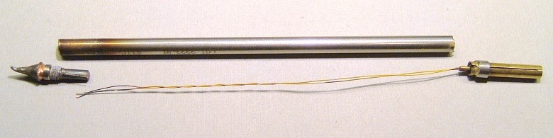
As you can see, there is no thermal sensor at all, the sting core is made of copper with a coating of ferromagnetic material, which is heated by a high-frequency (13.56 MHz) alternating magnetic field, then loses its magnetic properties at a certain temperature, called the Curie point, and , as a result, ceases to heat up. When you touch the place of soldering, the ferromagnetic element cools slightly, and the power from the inductor immediately begins to be transmitted to the tip of the soldering iron. The stings are with four fixed temperatures, of which in fact only two are needed - for lead, and for lead-free soldering. That's all.
OKI / Metcal produces several varieties of induction soldering stations of varying cost, and with varying output power, but the order of amounts around 60,000 rubles discourages any desire to touch the beautiful, no matter how beautiful it is. Well, let's try to save a little?
Task
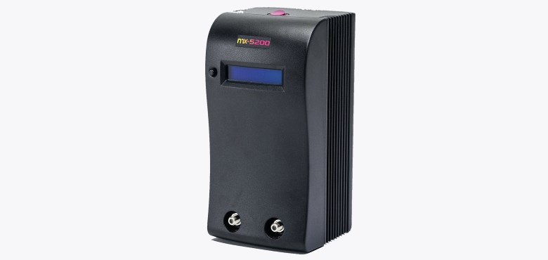
We formulate it as follows: using only open sources, conduct a virtual reverse engineering of the original MX-5200 device and, as a result, develop a single-channel sinusoidal RF voltage source suitable for production at home with a peak output power of 80W, as closely as possible the original soldering functionality station.
On the Internet, you can easily find the Metcal MX-500, a neatly copied
circuit from the previous generation station's station map. Directly to use circuit solutions from here will not work, since the output power of this device is only 40 W, and it does not scale in a simple way. However, this old scheme will help us understand the principles of the basic units.
So, in the document we see:
- Quartz powerful RF generator with three resonant circuits at the output;
- Pulse down-converter for supplying the generator (1), with output voltage varying in the range of 17-21 V;
- A feedback circuit regulating the voltage of the down-converter (2) depending on the voltage on one of the output resonant circuits of the generator (1);
- Protection unit, disconnecting the generator (1) when disconnecting the inductor;
- Transformer power supply with an output voltage of 53 V.
Immediately count up the general circuit solutions. For the power supply of the circuit, for example, a toroidal low-frequency transformer is perfect. Although ... and apply, we better resonant LLC-converter on a rare HiperLCS chip manufactured by Power Integrations: I have long wanted to work with it. Step-down converter used to adjust the output power also take a more modern, let's see whether you can really squeeze five amps from the body size of SO-8. But what is this project without arduino, sketch, and LED? Add an STM32 microcontroller and a screen to display the current output power. For simplicity, we will measure the power on the power line of the RF generator, and we will take into account the efficiency in the software (or we will not). We will take a metal case that is suitable in size; it will serve both as a screen and as a radiator.
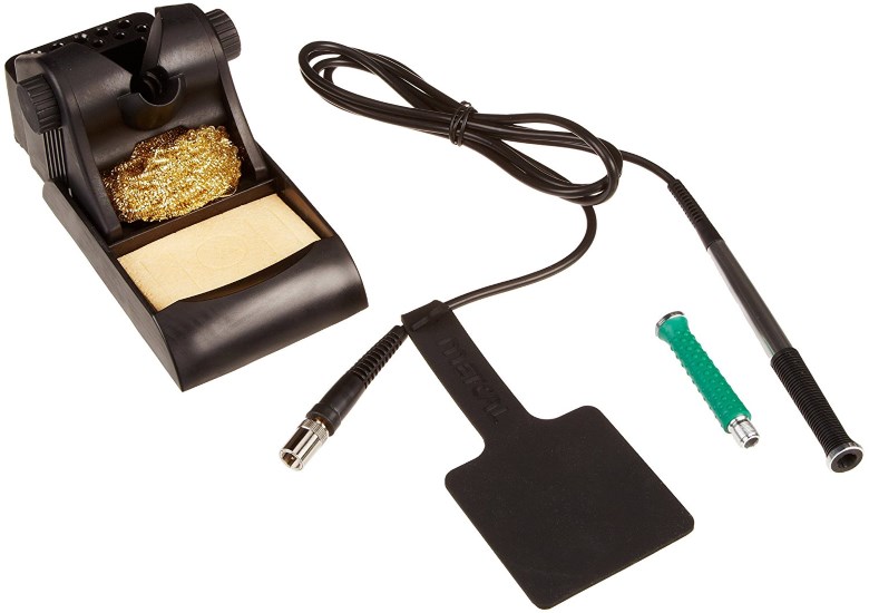
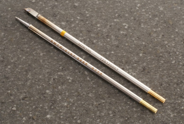
For directly soldering on Amazon, the Metcal MX-UK1 upgrade kit will be purchased, which includes a stand and the soldering iron itself (this is essentially just a wire handle), as well as the soldering cartridges themselves. Historically, it’s more convenient for me to work with so-called “hoof” (truncated at 30 ° cone), and for soldering massive elements it’s better to take something wider, more massive, and hotter, so here’s my choice: Metcal SMTC-0167 for fine work, and Thermaltronics M7K100 for working with large-sized elements. Yes, the cheaper Thermaltronics tips are also suitable.
While the details are on the way, let's draw a block diagram of the designed device. Here she is:
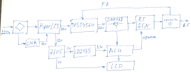
It is very important to immediately say a few words about the feedback between the output of the RF generator and the control input of the downconverter. The fact is that after the sting has reached the operating temperature, the generator continues to generate a voltage of rather considerable amplitude (about 100 V), and this power begins to dissipate on the active resistance of the inductor coil, which due to the skin effect is much more than you intend conventional multimeter. As a result, the tiny coil becomes red hot and burns. To prevent this from happening, negative feedback is used in the original stations, which reduces the generator supply voltage with a rise in the standing wave ratio that accompanies the change in the inductor impedance. In the 40-watt version, a rather simple method from the patent
US4626767A is used , and in the 80-watt version a more complex OS with a current transformer is used. Let's look at this video taken from the Internet:
The blue beam on it shows the supply voltage of the output stage of the RF generator, and, as we see here, we need to ensure that the supply voltage changes at least twice (the output power changes proportionally to the square of the voltage, that is, four times). I didn’t succeed in achieving such a level of regulation in the simplest OS scheme modeled in LTSpice, so we’ll simply draw a feedback loop from a photo of a PCB.
Rf generator
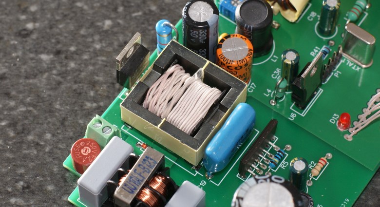
Designing the high-frequency part we start with the output resonant circuits. Let's take a look at this high resolution picture:
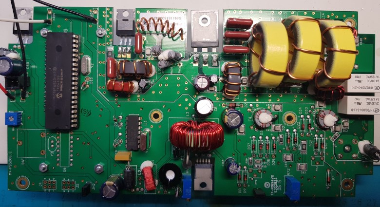
Here we see three coils wound on yellow toroidal cores, the number of turns is 4, 6 and 7, if we count from left to right. According to the classification of the company Amidon, yellow color denotes a core of sprayed iron with a magnetic permeability of 8.5 (material No. 6). We will estimate the size of the rings by measuring the size of a ring with a ruler on the screen, and the size of a known element, for example, an output transistor in a TO-247 package. Apparently, T130-6 magnetic circuits are used here; In my opinion, this is some overkill - such large rings are designed for significantly greater power. But I don’t have much desire to be clever here: I certainly will not use the original American rings, I’ll order inexpensive Chinese copies on AliExpress instead of them, let's see how they work (spoiler: everything is fine with them). The calculated inductances turned out to be about 180, 400 and 540 nH, respectively.
In the resonant circuits to the inductors rely more capacitors. Their capacity cannot be determined from a photograph, but a post is easily found in which the pedantic mikeselectricstuff (the author of the previous video) shares his observations (highlighted in yellow):
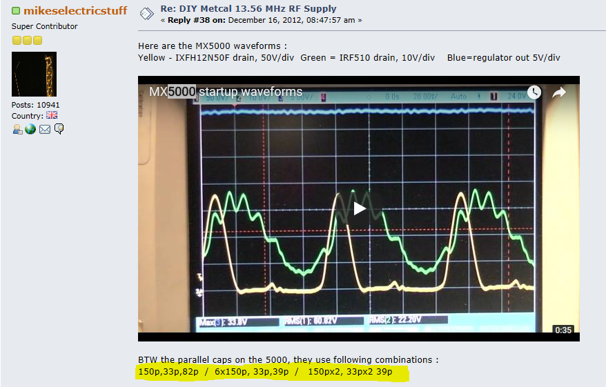
If we substitute these values into the spice model, we can see that the resonant frequencies of the circuits are slightly shifted from 13.56 MHz. The fact is that the closer the frequency is to the resonance, the less the supply voltage is needed for the RF generator, and the more current it consumes. In the original, a step-down converter with a maximum current of 3A was used to power the output stage, so the developers slightly disturbed the output circuits so that the supply voltage could be increased and the current consumption reduced. We are planning to use a five-ampere microcircuit, however, to work in the resonance of this current, it also turned out to be insufficient, therefore, in a similar way, we slightly upset the circuit. We will select the exact capacitance values experimentally, focusing on the maximum supply voltage of the 22 V output stage and the maximum current consumed at 4 A.
I note that quite a lot of power is circulating inside the resonant circuits, which still strives to be released into the environment in the form of heat. Therefore, in order to increase the quality factor for the coils, we use an enamelled wire thicker - 1.25 mm, and we will put the capacitors on several pieces in parallel.
Choosing an output transistor is also a difficult topic. When replacing or disconnecting the stinger, the overvoltage can reach quite significant values (300-350 V), but in the original the developer did not bother much with the protections, and put a rather rare, fast and expensive IXYS RF transistor with maximum drain voltage into the output stage 500 V. Of course, we cannot afford such luxury. Take the usual 200-volt field effect transistor STP19NF20 worth 34 rubles, and in parallel we will connect a suppressor for 150 V. Ideal! The limiter slightly cuts the tops of the resonant emissions, not allowing the circuits to swing too much, and after about 10 milliseconds after the load is lost, the protection will stop the generator.

Due to the large input capacitance and high frequency, it will not be possible to control the output transistor gate directly with the help of a regular driver. The photo of the original board between the two power transistors can be seen frameless inductance. This is a widely used little trick: the inductance, together with the gate capacitance, forms a resonant circuit that provides recirculation of power in the gate circuit, resulting in a dramatic increase in the efficiency of the preamplifier. The same circuit simultaneously imposes an unobvious limitation on the output transistor model: its gate resistance should be minimal so that the Q-factor of the circuit remains acceptable. Not going into much detail, we repeat the solution used by the manufacturer. The inductance value is selected by the maximum efficiency of a real circuit by compressing / stretching the coil turns.
Well, then circuitry becomes more trivial. The preamplifier, made on a transistor with a low input capacitance IRF510, will be swung by the dual driver
MAX17602 , its speed characteristics are quite good. MAX17600 or MAX17601 will be even better, their outputs could be connected in parallel, but I did not have such options, so we will work with what we have.
The desired oscillation frequency is set by a quartz resonator. Unfortunately, I also failed to find quartz at 13.56 MHz for the master oscillator. But it does not matter. Take the more common resonator at 27.12 MHz, and divide the frequency in two. This is where the microcontroller comes in handy, namely one of its timers programmed accordingly. I would also like to note that for direct connection to the MCU, only quartz resonators operating on the first harmonic are suitable. The widespread 27120 kHz Russian resonators, operating on the third harmonic, can only be connected with a crutch in the form of an additional resonant circuit.
Nutrition
After long and fruitless experiments with products of the Chinese industry, it was decided to power the RF output cascade from a down-converter on a TI
TPS54560 microcircuit from TI. The frequency of the internal oscillator to exclude the occurrence of audible ear beats is set to approximately 450 kHz, away from the frequency range of the LLC-converter. There is also an option to do the opposite, to synchronize the step-down converter with the LLC-converter generator, but then laziness has already begun to make itself felt. We will not do that.
The TPS54560 converter itself, despite its miniature size, has a rather large output current, and sometimes it may seem that this is some kind of hitherto unseen miracle in the struggle for energy efficiency ... But no, the chip needs really good cooling. The Texas-offered demo board contains two large “earthen” polygons with a thickness of 2oz on both sides, and for the heat transfer between the layers, six transition holes are used, located directly below the integrated circuit (there it has a heat sink). Such an arrangement makes it difficult to manufacture PCBs at home, so you will probably have to order production in China. Eh.
To power the driver and the preamplifier, take the unstabilized voltage of 12V from the second winding of the LLC-converter. The consumed currents of the remaining parts of the circuit will be quite small, so for the five-volt controller and LCD backlight within import substitution, we put the linear regulator KR142EN5A, designed specifically for use in the national economy, and the line of 3.3 V for the MCU will be provided by the
bog LD1785 .
Reducing the mains voltage to the required 30 and 12 volts will be carried out by LLC-converter on the
LCS708HG chip.
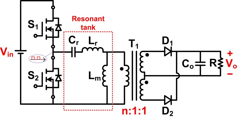
I am sure that many readers are not aware that it is generally for such a beast - LLC-converter, so I’ll dwell on the principle of its operation in a little more detail. LLC is not exactly an abbreviation, these letters mean "inductance-inductance-capacitance", and, in brief, describe the circuitry of connecting the transformer primary winding. The fact is that part of the magnetic field lines of the primary winding does not “hook” to the secondary coils, resulting in the so-called leakage inductance - parasitic inductance, which is not capable of transferring the accumulated energy to the secondary circuits. In conventional flyback converters, this energy has to be dissipated on suppressors or resistors of snubber, therefore, transformers (or, more precisely, double-wound chokes) are usually designed in such a way as to reduce leakage induction to the lowest possible value. But everything changes when you construct an LLC.
In the resonant converter, the leakage inductance together with the primary winding connected in series to the capacitor form an oscillating circuit that performs two important tasks. First, it provides switching of the output high-voltage transistors of the converter at close to zero voltage (the so-called Zero Voltage Switching mode), which drastically reduces switching losses. And secondly, the energy accumulated in the uncoupled inductance is returned back to the circuit: now snuffers are not needed, and there is no energy loss either. Power Integrations's
AN-55 describes in detail how to design a transformer in such a way as to increase the leakage inductance (this is necessary to create the right adjustment characteristic). For example, I wound the primary and secondary windings away from each other, in two different sections:
In the general case, the result of such circuit design is the achievement of a very decent efficiency, in particular, the LCS708HG installed without a radiator, with its very small dimensions, provides an output power in the region of 200W! This is a truly outstanding result, but it can only be achieved by operating at exactly the resonant frequency of the output circuit. And here we are lurking ambush.
The point is that the regulation of the output voltage here is carried out by changing the frequency, not the duty cycle of the pulses, and this regulation is limited to a very narrow voltage range - approximately ± 15%. Moreover, when the input voltage deviates from the nominal, the conversion frequency shifts away from resonance, and the switching of the transistors inside the chip becomes “hard”, with loss of ZVS, which is accompanied by their significant warming up. In fact, it can be said that the converter requires a stabilized voltage at the input!
In industrially manufactured products, before entering the converter, an active power corrector (APFC) is turned on, which, in addition to the power correction itself, also maintains an output voltage of approximately 380-390 volts. However, our development is still an amateur, therefore, we boldly close our eyes to the small joint in the form of sensitivity to the quality of the power supply. Calculations show that, taking into account the pulsations on the buffer capacity, the input voltage range corresponds approximately to 230 V ± 10%, so if the network parameters do not go beyond GOST, then everything will work. Leave for now.
The rest of the circuitry constructive transducer copy from datasheet. Perhaps only a resonant capacitor was required to give a bit of attention - at first glance a very simple element. And if you have ever wondered what is the difference between polypropylene and polyethylene terephthalate (polyester) capacitors, then you will know the answer right now: the first loss tangent is ten times smaller. That is why the attempt to use the cheaper and more compact polyester K73-17 instead of the overall K78-2 (yes, here is also import substitution) is accompanied by interesting special effects: the capacitor warms up a lot and starts to crackle suspiciously. It is interesting.
The HiperLCS series chips require a separate 12 volt power supply. In order not to bother with the additional winding, rectifier and trigger chains, let's go, perhaps, on the most canonical way. We take the required voltage from a separate miniature transducer on the
LNK304 chip. Its key feature is a transformerless design, from the inductive elements you need only a factory made kopek choke. The maximum output current is not very large, on the order of hundreds of milliamperes, but the minimum of details and simplicity of construction are captivating (and the number of converters per square decimeter of the surface begins to unnerve. More converters to the God of Converters!)
Brain
Well, only a little remains. In the original station there is an LCD, which for all the money paid shows something like an output power. Let's do the same thing: take the STM32F030 controller in the most minimal configuration (in the TSSOP-20 package), hang one ADC line to measure the supply voltage of the RF generator output stage, another line to measure the current. In order not to break the “earth” circuit, we place the resistive current sensor on the positive wire, and to convert the levels we will use the
INA138 chip specially designed for such cases, which Burr-Brown developed at its best times. To display the information, we use a text OLED-screen size 16x2 produced by WinStar. Well, that's all. Oh, well, one leg of the processor remained idle. Well, let the flashing LED. Do not ask why.
The controller firmware is written in the “C” language using the STM32CubeMX and the free version of IAR Embedded Workbench. The software code is quite trivial. The main loop for interrupting the system timer, every 300 milliseconds, reads data from two ADC channels, multiplies them, and displays them in the form of power digits. From below, the same power is visualized by a strip drawn by custom fonts. When the sting is disconnected, the interrupt handler from the output of the load detector is stopped by the setting timer of the RF generator. In case of a crash or MCU failure, hardware error and watchdog handlers have been added; Also, CSS (Clock Security System) technology is involved in the firmware, which in case of damping of the oscillations of the main quartz resonator, switches to the internal RC generator and restarts the microcontroller. The total amount of firmware - 10 KB. The source code of the firmware along with all the other project files I posted on
GitHub , the most curious can read (but do not expect there is something very interesting).
Constructive
The device contains several custom coils- The chokes in the drain circuits of field-effect transistors and the current transformer in the feedback circuit are wound on rings K16x8x6 in size made of ferrite M50VN. The joke about “finishing with a file” will be most welcome here: the Russian industry still seems to have not learned how to make ferrite rings with rounded edges. The enameled wire is suitable for a diameter of 0.6 mm, the number of turns is 15 for chokes, and 2x14 for the current transformer;
- Frameless coil is wound on a frame with a diameter of 5mm enameled wire with a diameter of 0.6mm. It contains 10 turns and has a length of approximately 10mm;
- - EFD25 N87 Epcos. , ( 0,1). (26 ) (5 ) 100/46 175/46 ( – , – American Wire Gauge). , 12- — .
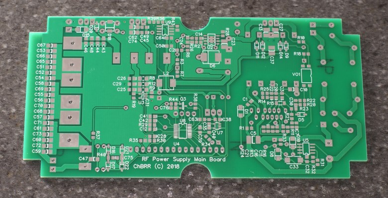
All design data of all elements of the LLC-converter, including inductors of transformer windings, are given in the design file attached to the project, which can be opened using the PIXls Designer application. Also, just in case, I added to the project all the documentation used for the development of the applied electronic components, I filled in LTspice models of some parts of the circuit, and, of course, fotochki, which is now without them.The result of the above development was the following electrical schematic diagram: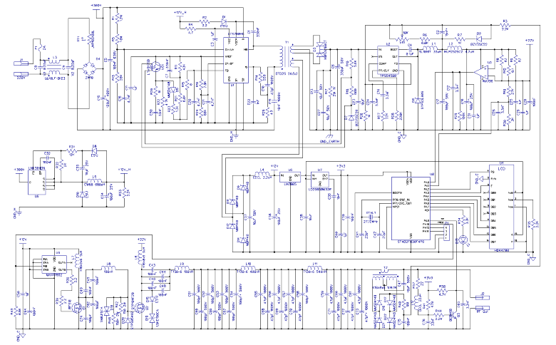 The layout and layout of the PCB were rendered in the DipTrace package, and the board’s drawings were converted to Gerber format to be sent to the factory. The board is divorced exactly to the size of the used case, for shielding delicate low-current circuits, one layer is entirely cast under the “ground”. Such wiring greatly simplifies the manufacture of the board at home, as there is no need for precision alignment of the photomasks: almost the entire back side of the board can be filled with one solid polygon, and then chamfered at the pin holes that do not require a connection to the ground.
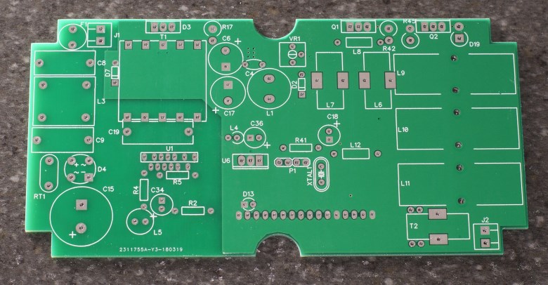
 The high-frequency generator of the structure decently whistles on the air, the power elements heat up strongly, so the choice of material for the body is self-evident: of course it will be aluminum. Let us select from the Gainta catalog of an approximately suitable finished G0476 housing. We cut the window for the OLED screen in the case with the help of a Dremel; we connect the case itself directly to the ground cable of the power cord together with the screen of the soldering iron wire and to the weight of the printed circuit board.Unfortunately, the idea to connect a more contrast OLED instead of LCD came to my mind after the order for the boards was sent to the factory. CMOS input levels OLED-screen WEH001602AGPP5N00001WinStar production differs from standard TTL-levels of LCD, so that the feint with ears, when + 5V is fed to the display controller and its backlight, and logical signals are taken from the microprocessor with a power supply of + 3.3V, does not roll here. Therefore, the power of the screen had to be wired from the 3.3V line.To reduce the level of interference, a noise-canceling resistors with a nominal value of 390 Ohms were added to the “cable”, and the microcontroller was covered with a screen made of copper foil. During normal operation, the mating part is attached to the programming connector, which draws the debugging outputs directly to the “ground”, and the NRST - via the capacitor.In the end, the developed device took a finished look:
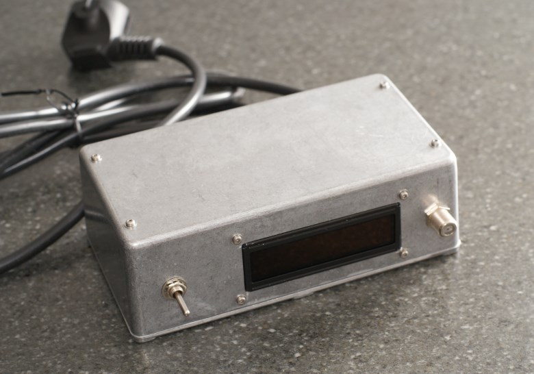 Now the heating up of the soldering iron looks like this:
Banquet
Now let's roughly estimate what this entertainment cost us:Radio components - approximately 3000 rubles (the most expensive elements here are the HiperLCS chip for 1000 rubles, and the OLED screen - another 600 rubles);Manufacturing of printed circuit boards, cost for 10 pieces - 2,700 rubles;Case - 500 rubles.The total cost of the high-frequency power supply proper was approximately 6,200 rubles. Also, extra money was paid for a soldering iron with a stand (11,000 rubles), and for two cartridges (6,000 rubles).Of course, these amounts can be slightly optimized, for example, on eBay, a wide range of used Metcal components are used, in which case we can talk only about a few dozen dollars, but this is probably a matter of personal preference.Errata
- The driver and preamplifier stage power supply could be taken less than ten volts instead of twelve, changing the ratio of turns of the secondary windings 2: 6 instead of 2: 5, with a corresponding recalculation of the turns of the primary and the capacity of the resonant capacitor. In this case, not only the driver and the transistor of the preamplifier will be less heated, but also the magnetic core of the network transformer;
- Turning off the soldering iron at a working station is not supported, sometimes this leads to a restart of the microcontroller. We need to think about additional shielding of the high-frequency part (but this is not accurate).
findings
Well, now the most important thing for the sake of which it all started: the sensations from working with the device. Feels as if you are working with a very powerful and very hot soldering iron, while holding a small and light tool in your hands. Is it worth the money and effort? It is hard to say.
I leave this question open.