Hello! I am Artem Litvinovich, a developer with many years of experience, a radio amateur since childhood, and I myself designed readers. In my opinion, to do it yourself for your requirements - it is more interesting and more convenient than buying a ready-made thing. For example, the same reader. On my account - four personally assembled models of readers from components found on the radio market and ordered from China.
For example, e ink is described
here , it is still Leonid Kaganov
here considered, the earlier crafts are all
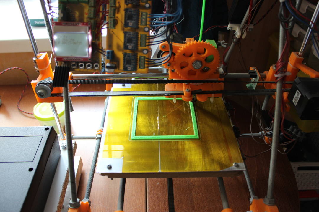
here . I print the cases myself on a 3D printer, which I also designed by myself. And when I'm too lazy to type, I sculpt from epoxy.
Experience, as you understand, has accumulated a very serious and to some extent unique. So, the guys from PocketBook approached me with a proposal to make a mod of one of their models. In the end, we decided to assemble a reader with a solar battery based on
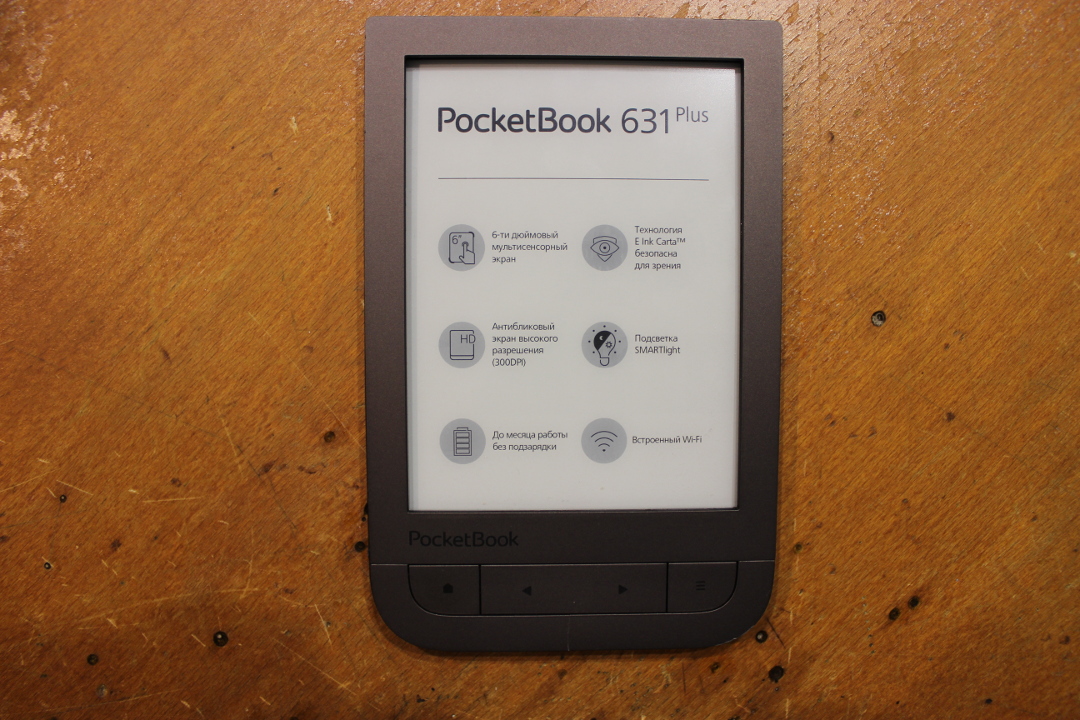
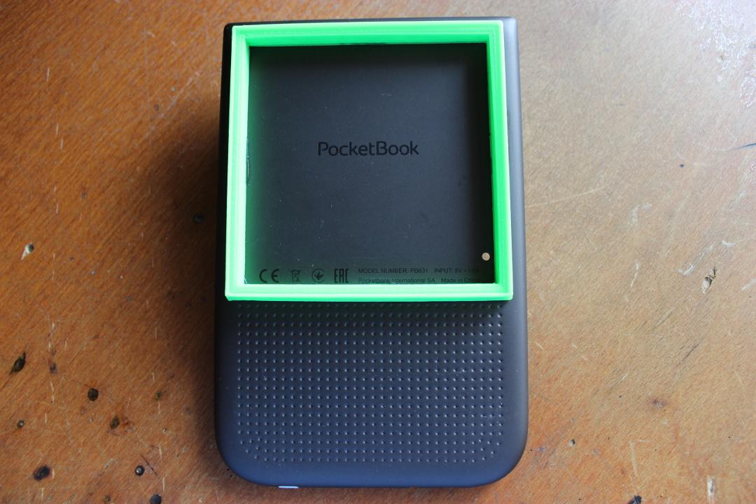
PocketBook 631 Plus , one of the flagship readers of the line. About this I will tell in the post.
I will not go into the details of the functioning of this model from a user point of view. Many wrote how many formats it supports, what applications it has, how audio support works, and how well this poketbook pronounces books in fifteen languages. I will only note that, in general, I agree with these statements - the reader is hard-boiled and really heaped up.
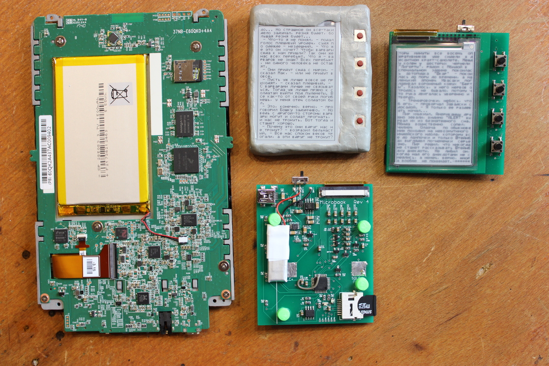
Having received a reading room on my hands, I did not even turn it on - I immediately took it apart. Therefore, we begin with an inspection of what is inside her. This is more interesting for me. Disassemble the reader - it's easy, just one, two, three. Go!
Once - using the plastic wedge snap off the front panel.
Two - gently peel off the screen frame from the front panel. I suspect that it is sealed to complicate the ingress of moisture and dust inside through the gap. In
PocketBook 631 Plus , unlike the same
PocketBook 641 Aqua 2 , officially protection against water is not declared. And yet the "rudiments" of protection are present here. With such elements of construction, the spray of moisture of this model, I suppose, is not very scary.
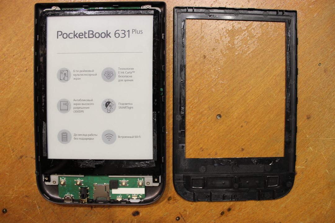
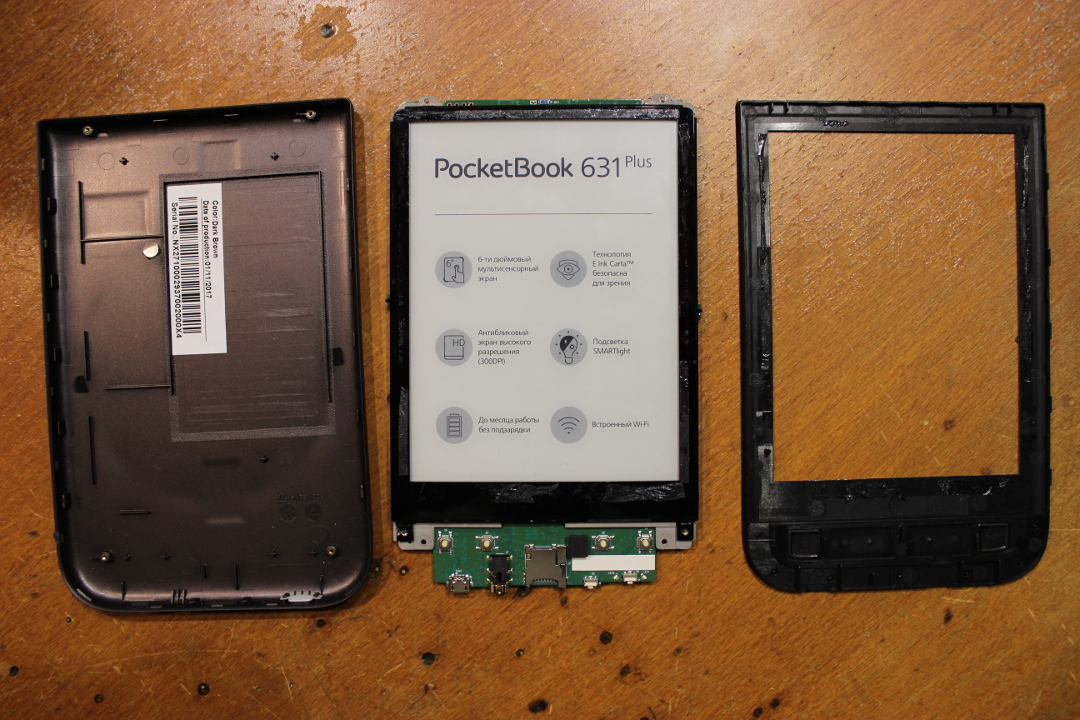
And three - unscrew the screws holding the reader itself in the case.
What is the modern reader?
To an innocent eye, it may seem that everything is terribly complicated, but, in general, the device is quite simple.
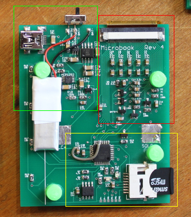
For simplicity, compare with my homemade reader, which is on the right.
Three blocks are clearly distinguished on my board.
- Red - screen power scheme. The electronic ink screen is electrostatically controlled and requires several voltage levels, positive and negative.
- Green - power, charge and discharge controller. Lithium batteries are charged with direct current and give non-constant voltage. Electronics requires constant 3.3V. Solar panel gives uncomfortable current. Accordingly, a DC controller is needed for charging, a voltage converter for discharging and a power limiter for the solar panel.
- Yellow - computer unit. There is a processor, memory and data storage, with all the strapping.
Surprisingly, in essence, the reader is just an energy-efficient computer with a special screen and software.
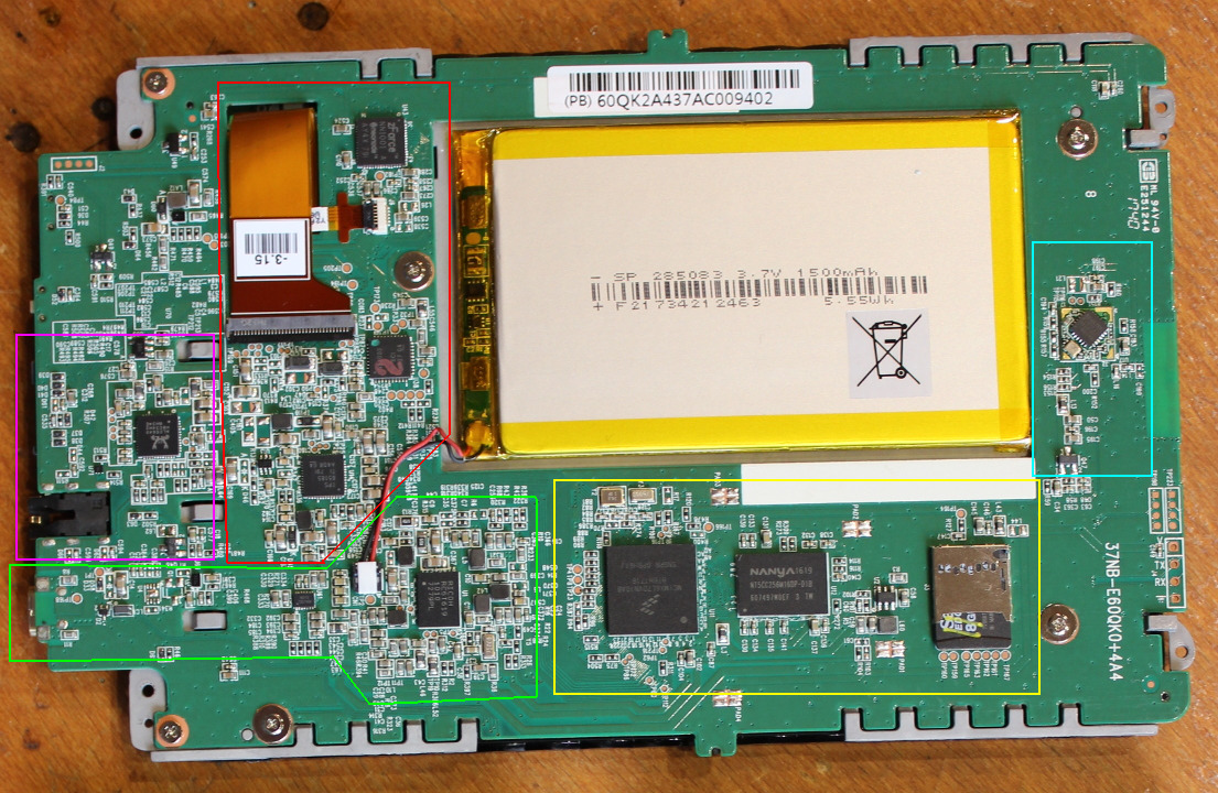
Now take a look at the insides of the PocketBook reader
Here you can see similar blocks - power, work with the screen and the computer. Additionally, there are two more blocks - a blue Wi-Fi module and a pink audio codec. The latter is quite atypical - in almost all modern readers with E Ink screens there are no sound capabilities. Their presence is one of the unique "chips" namely PocketBook 631 Plus.
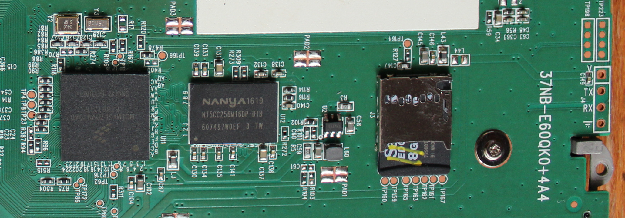
Look at the insides of the PocketBook reader more closely.
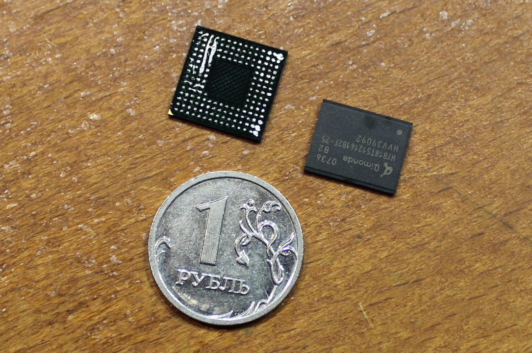
The processor module, MCIMX6L7DVN10AB, is viewed on the processor module. This is ARM Cortex-A9, single-core, 32-bit, nominally 1 GHz. Stuck significantly more powerful than used by me. What is not surprising - Pocketbook reads without preliminary conversion 18 formats (PDF, PDF-DRM, EPUB, EPUB-DRM, DJVU, FB2, FB2.ZIP, DOC, DOCX, RTF, PRC, TCR, TXT, CHM, HTM, HTML, MOBI and ACSM), as well as voiced text, climbs the Internet, plays games and is able to arrange hyphenation. For the maintenance and implementation of all this good, you need the appropriate iron.
To the right of the processor is the memory, NT5CC256M16DP. This is DDR3, 4 Gbps (512 MB).
Behind the memory is a regular MicroSD connector with an 8 GB card, which plays the role of built-in storage. Cheap, cheerful and convenient -
if you wish, internal memory can be easily expanded (Check showed that the card is tied by some hardware identifier, so the word “easy” is inappropriate in this case), and in the case of a catastrophic meeting of the reader with the earth's firmament, data recovery will require only a card reader.
On the card is found ordinary Linux, which pleases. On the right is the UART debug connector. If we poke a probe into it, we see the U-Boot 2009.08 splash screen and a bunch of debug information.
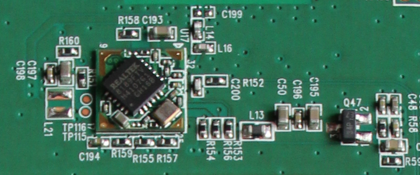
Next to the processor module is a Wi-Fi unit with a switch and strapping. RTL8189FTV, 802.11b / g / n all-in-one module, connected via the SDIO bus.
Putting ready-made modules for this type of functions, and not unzipping them discretely on the board, is one of the standard practices in the development of electronics.
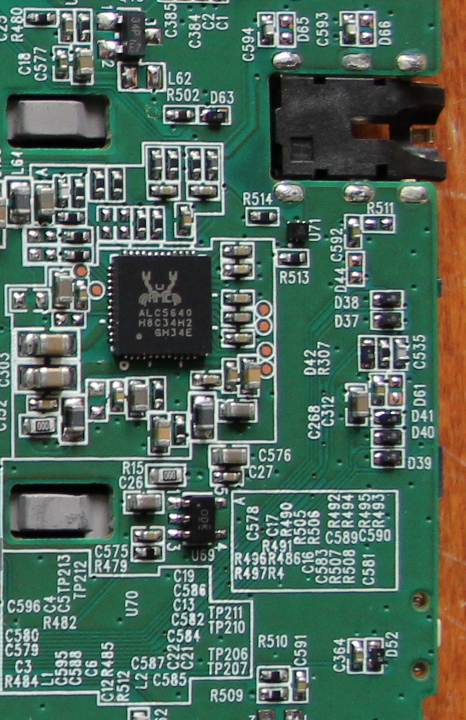
On the far side there is a codec - a sound converter from digital to current on headphones. ALC5640 of the same Realtek company, it takes sound via I2S and outputs 1.5 W stereo sound to 8 Ohm speaker through a class D amplifier. Also a typical thing.
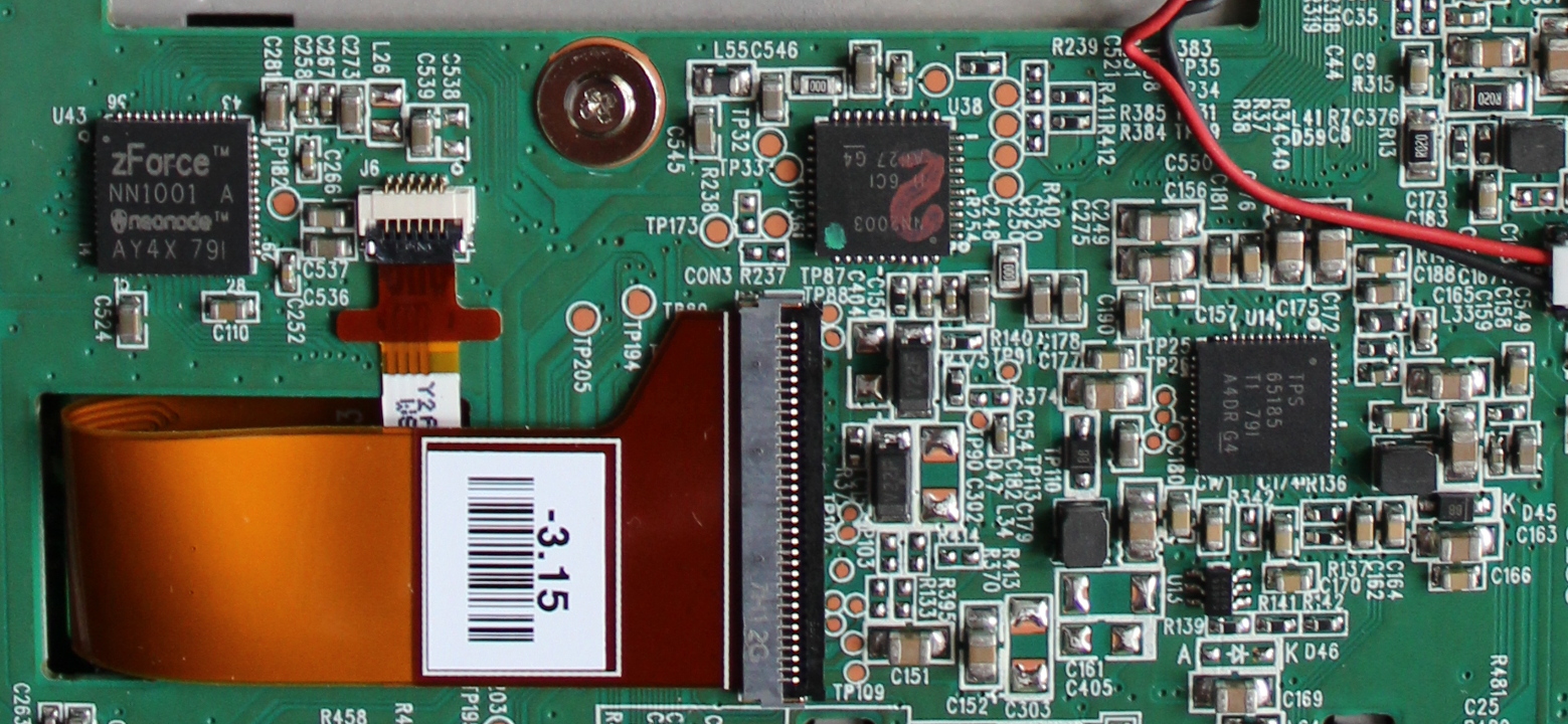
Above the sound is a screen control unit.
TPS65185 is a voltage generator for electronic ink screens. NN2003, or something like that with “2” on top of the marking could not be identified, but it looks like something related to the power of the backlight. And the zForce NN1001 is sort of like an IR touchscreen controller.
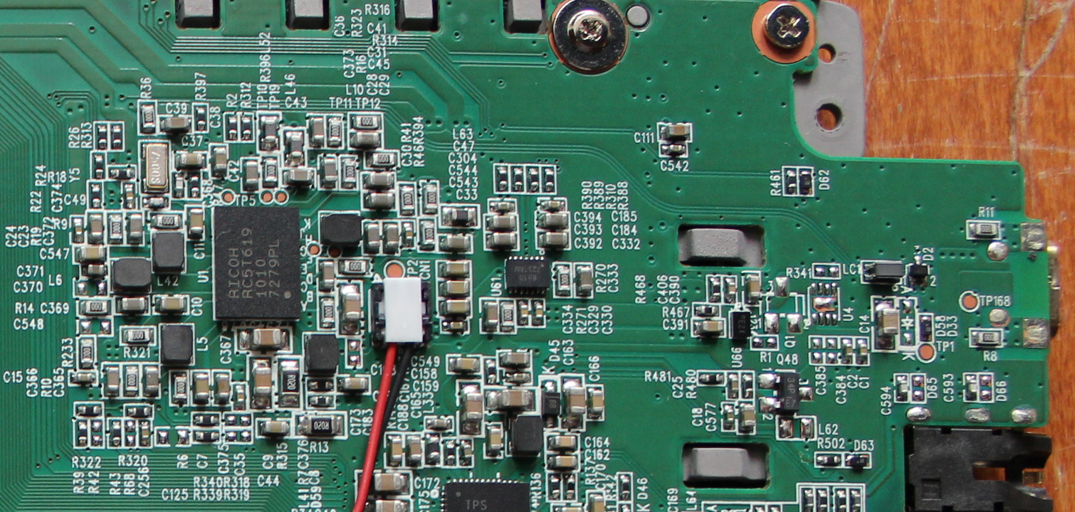
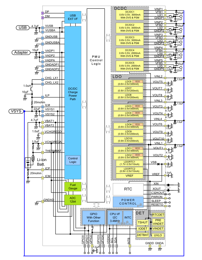
Finally, the main power supply. In the center is the main chip - RC5T619. It is a multifunctional power controller with built-in converters, consumption counting, battery charging, interfaces for communicating with the processor, etc. It also has a real-time clock that must walk even when everything else is turned off. Such a highly integrated power supply plays a significant role in the fact that one reader lasts about a month and a half of active use. We will look more closely at this microcircuit later when we attach a solar panel to the reader.
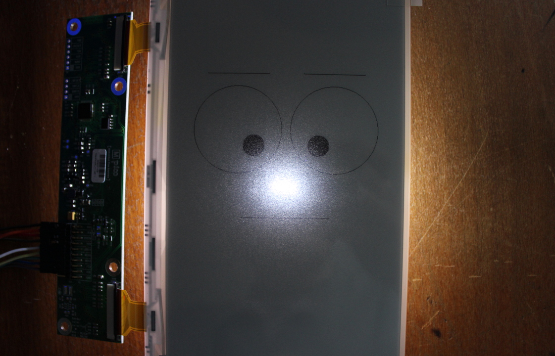
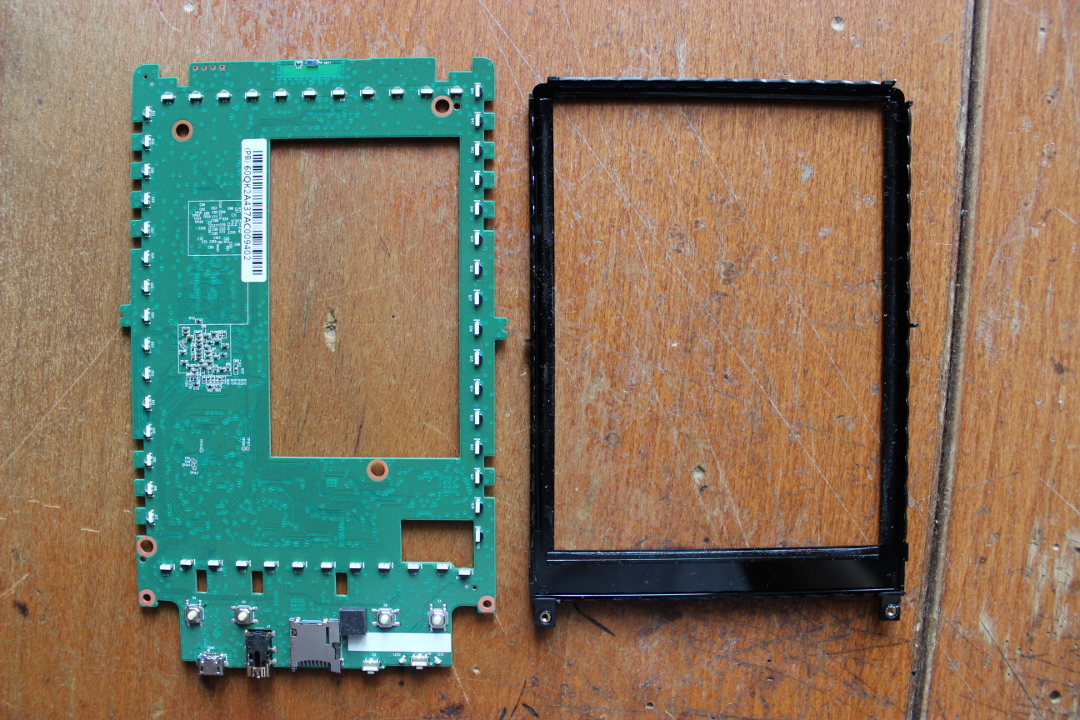
Turning the board over, we discover the screen — the most interesting part of this book.
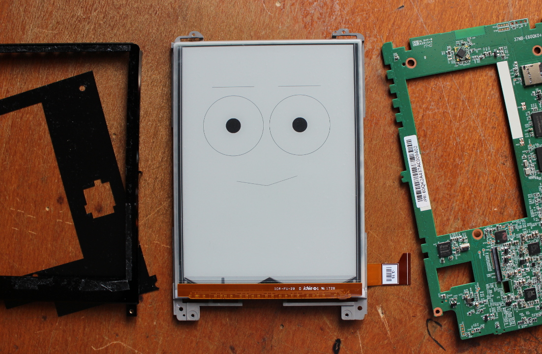
The screen is glued to the frame, on the other side of the frame the battery is glued. The board is screwed to it, and to some extent the whole case.

How much does this 6-inch screen of the latest generation, “E Ink Carta”, differ from the usual E Ink screen that you can buy in a store?
For comparison - this is my 7-inch screen of a Chinese company.
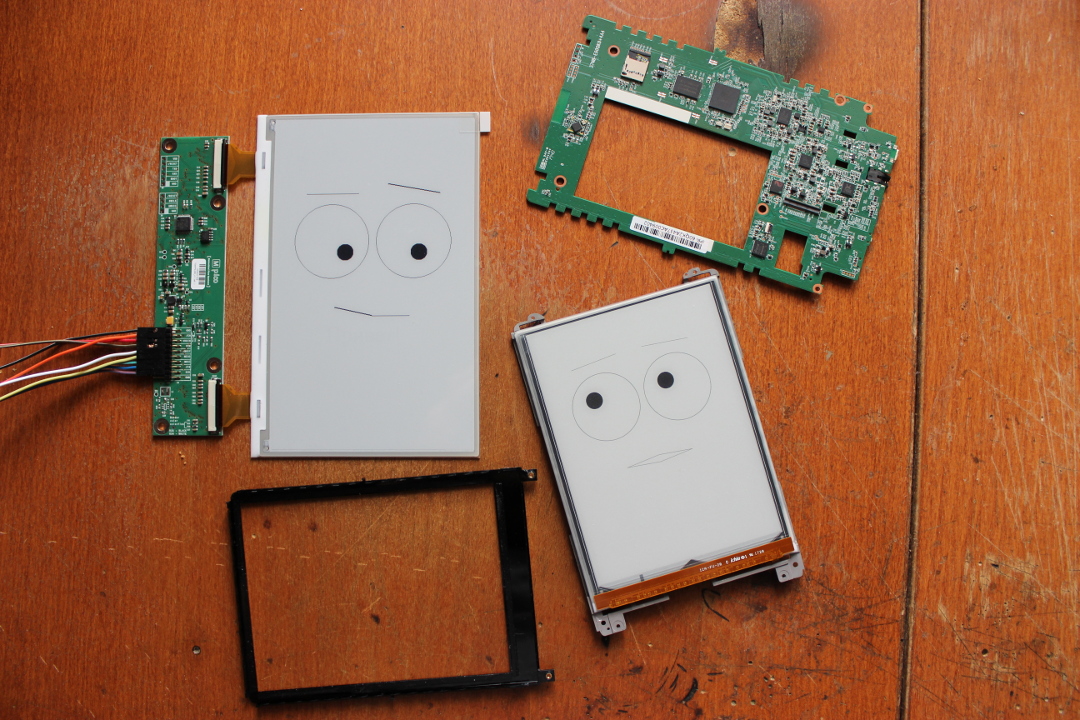
By putting the same picture on both of them, you can immediately notice the differences. My screen, although larger, has only 480 x 800 resolution and 120 DPI, while the resolution has 1072 x 1448 and 300 DPI. Well, the quality of the matrix itself is higher - as a major first-tier manufacturer, PocketBook uses the highest quality displays - Grade A (“first grade”, before rejection). Smaller brands, and for sale in the form of spare parts, comes Grade B - screens with some (permissible standards) number of defects.
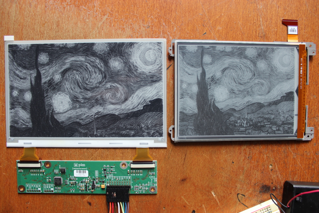
If you look closely, you can see another big difference - on the Poketov screen, the “colors” are smoother.
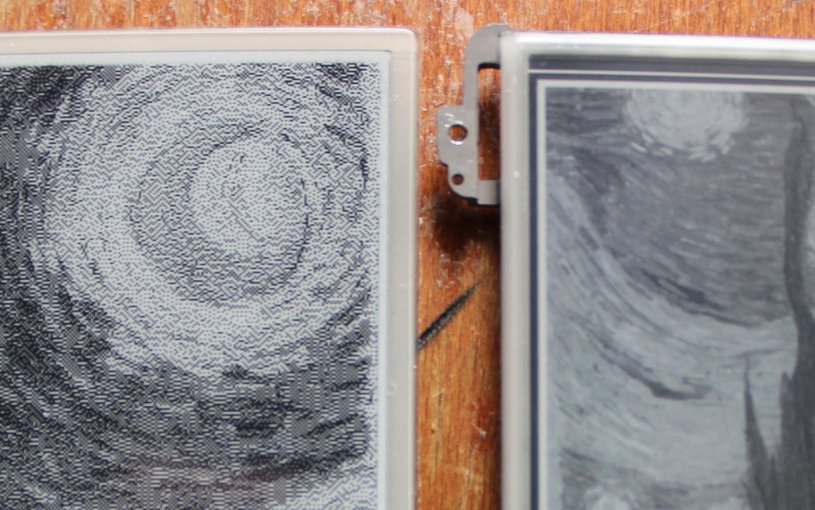
This is not surprising, since, in contrast to the black-and-white “Chinese”, the screen is monochrome and supports
50 16 shades of gray.

In fact, this is not the merit of the screen (although it is, of course, also its merit), as more sophisticated than me, the control circuit. Fundamentally, these two screens are not very different from each other, and the main difference is in the strapping.
Look closely at the technology itself. An electronic ink screen is such a glass, on one side of which there is a matrix of control electrodes, and on the other, an array of bubbles with a liquid sealed in transparent plastic, in which microscopic balls float. White is positively charged, black is negative. The control matrix rotates the balls electrostatically, thereby displaying an image on the screen.
From the back side, such a screen is mirrored, and the wiring of control signals carved on the glass is visible.


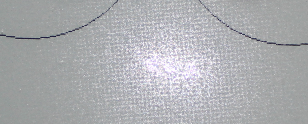
If you look at the screen in the light, you can see a thin control grid behind the noise of unevenly applied capsules. Due to this irregularity, the backlighting of the electron-ink screen is quite a non-trivial task - if you just highlight it from behind, it will look like a glass crumb.
Something it even resembles ordinary paper.
The screen of the pocketbook is tightly glued to the frame, and attempts to separate them, most likely, will end sadly. However, there is a place on the edge where it can also be enlightened and see a similar structure.
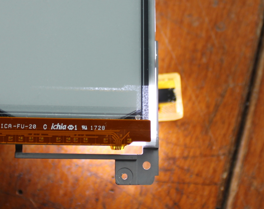
We see that on top of the screen is a black frame, and on the board below it - a set of some details.
What is it?
And the frame is not simple, but transparent in infrared light! And the protrusions on it look like lenses. What is all this for?

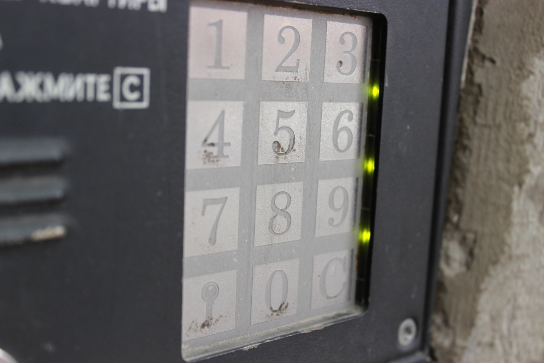
The riddle is solved very simply. We recall the usual intercom with an iron keyboard, which strangely ceases to work when its edges are smeared with snow. Along the edges of this keyboard is a set of light and photodiodes into which they shine. By tracking the shading of this illumination, the processor can understand which digit a finger has appeared on.
In our e-book reader, the design is similar, only more precise. At the edges are infrared LEDs, which frame focuses on the photodiodes on the opposite side, and the processor calculates the location of the finger by shading.
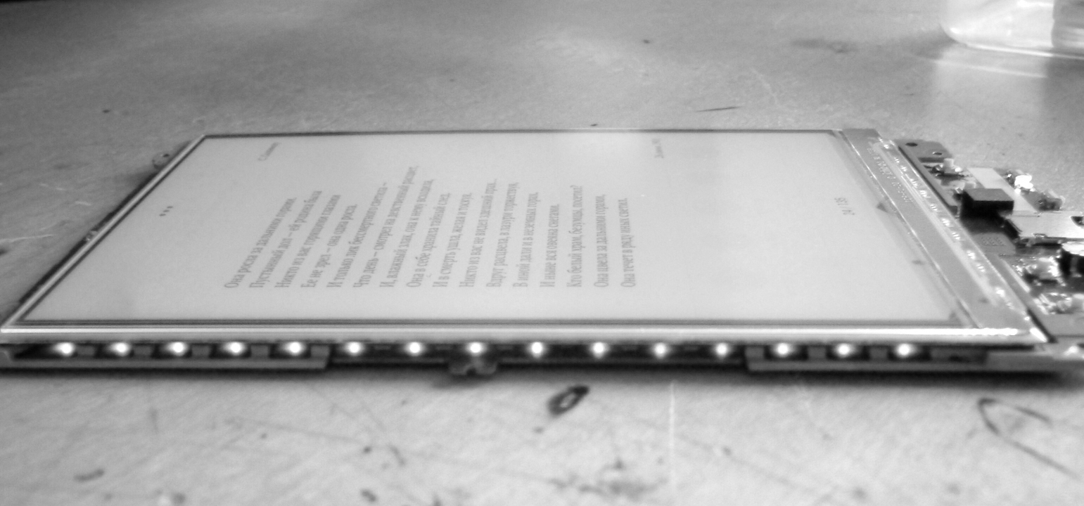
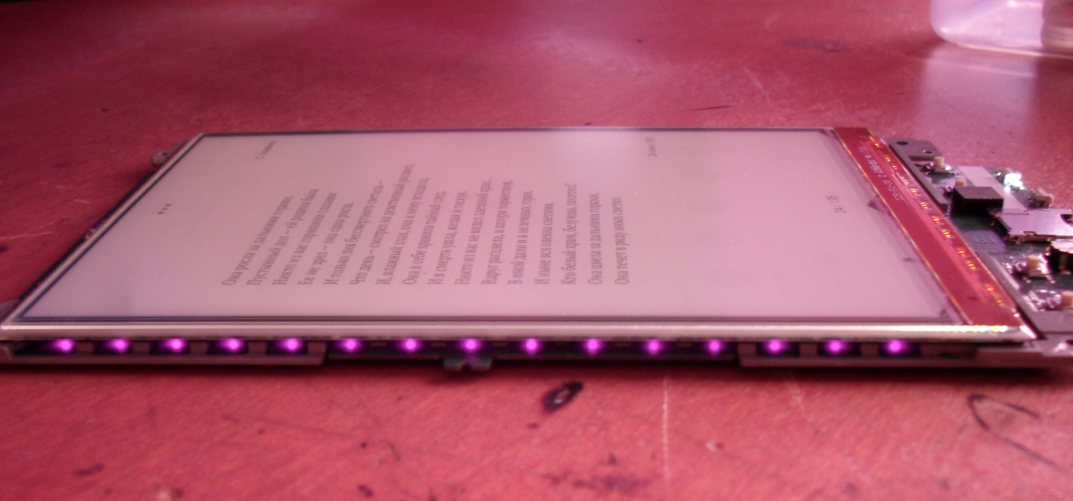
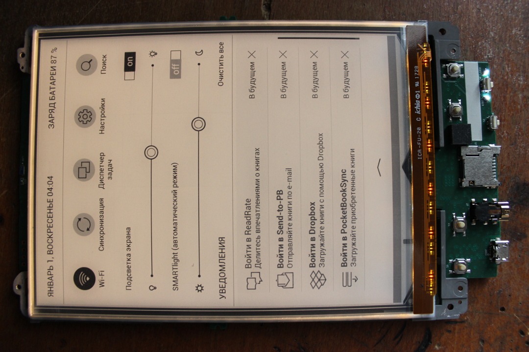
Below the screen is pasted with a strip of flexible board with LEDs. This is the most famous light with variable temperature light. If you go to the left, the light gets colder, to the right, it gets warmer. The idea is this: before bedtime it is better to read with warm illumination, thanks to which the visual apparatus relaxes faster. There are two variants of such a backlight, one designed by E Ink, the other is its Chinese copy. A copy is worse because it eats about a third more energy. The PocketBook 631 Plus is the right, E Ink.

 You go to the right - the light is warming
Like everything brilliant, the secret is simple - the backlight consists of alternating LEDs: warm, cold, warm, cold, etc.
The brightness of each half is controlled independently, which allows you to smoothly move from cold to heat.
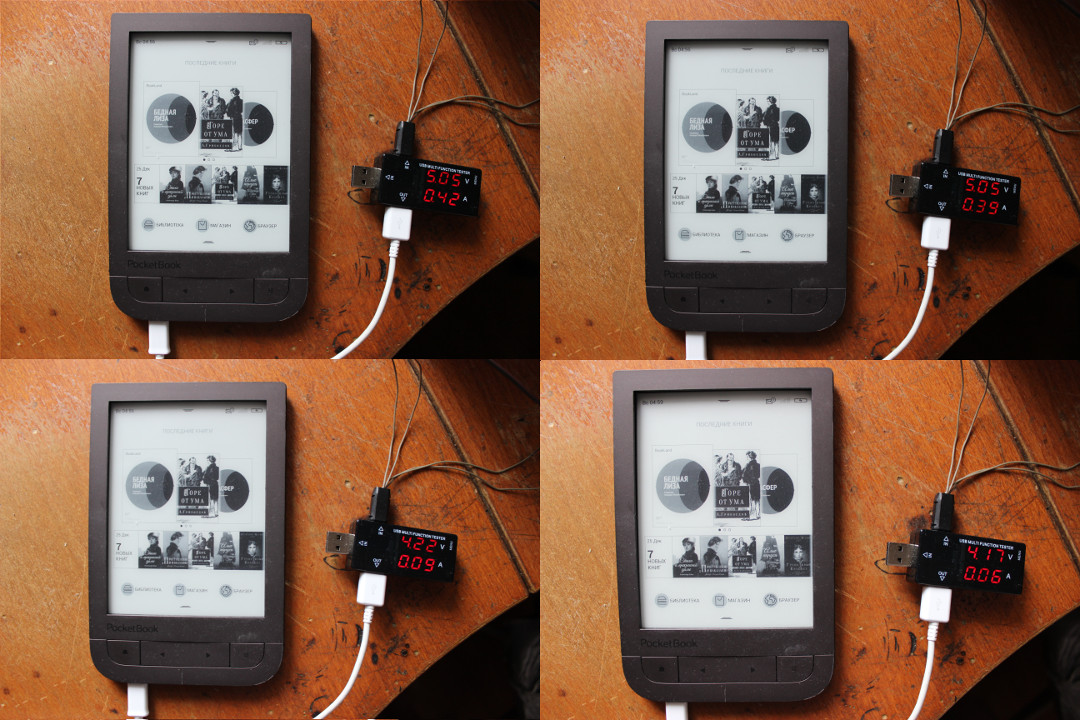
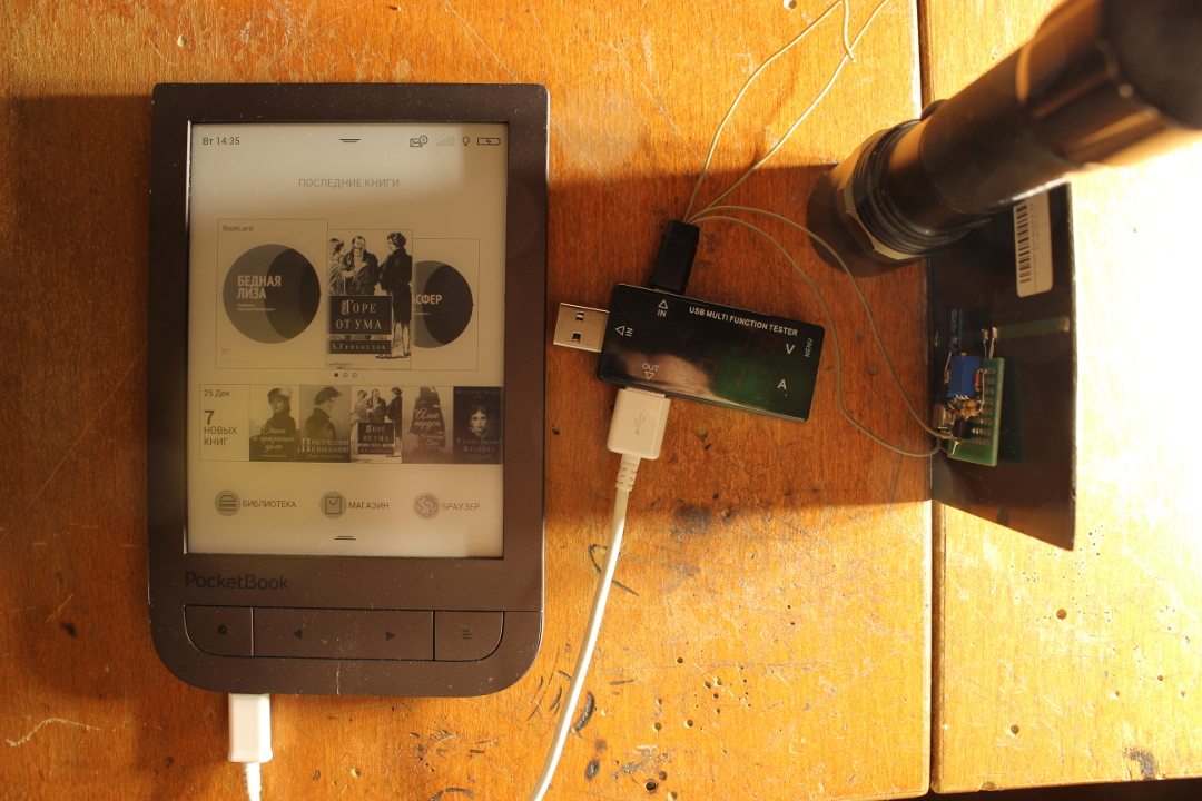
On this review, you can finish the viscera, reassemble the reader and go on to charging. Under normal conditions, the book is charged from a standard USB with a current of 0.9A.
This is 4.5 W, and should provide a full charge of its 1.5A / h battery for about an hour.

As the available current decreases, the book continues to calmly charge up to almost zero. It seems that the charge controller is of little interest to the USB standard, and it can charge from any voltage up to the voltage on the battery itself.
What generally happens when charging and discharging? We recall the RC5T619, which controls the power subsystem. It is an integrated controller of power, charge and consumption calculation. It has two channels to the input for charging and external power, built-in voltage converters, output to the battery and outputs to the consumer, sensor inputs (for example, battery temperature) and much more. All this is configured both at the circuit level and programmatically via an I2C bus.
On the same bus, the processor receives information from it about the remaining charge in the battery, charging status, current time, etc.
What is the difficulty in determining the level of charge of a lithium battery? Can't you just measure the voltage on it? Alas, the voltage on it is nonlinear, for the most part constant, and strongly depends on the load.
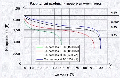
In practice, to determine the level of charge is used counter pendants. Similar to an electric meter in an apartment, he considers how much charge has flowed from the battery to the load and from charging to the battery. This is the only reliable way to reliably show the battery level. And such a counter is usually built into the power controller. The process of charging a lithium battery is also not easy, unlike, for example, from the lead. The charging process consists of two stages - direct current and constant voltage. At the first stage, the current is limited to the maximum safe value, usually in 1C (one battery capacity per hour). When the battery voltage reaches its maximum value (4.20V), the second stage begins when this voltage is maintained at the input and the current drops. In the end, the current reaches a lower threshold, usually 0.1C, and charging stops there.
All this, again, is engaged in an integrated power controller.
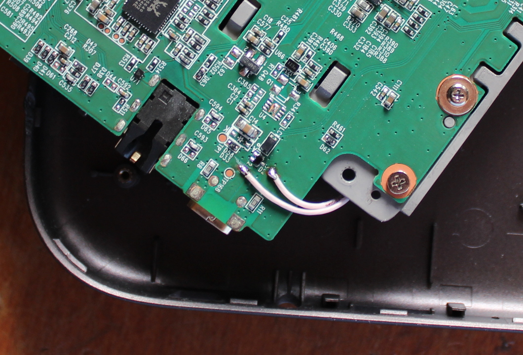
Obviously, to connect another power source will need to go through it. Ideally, you could use the second charge input, VADP, but there is a small problem - on the board of our reader it is not divorced, and the controller is a BGA chip, a plastic rectangle with contact balls on the bottom side, and get to the VADP inputs, essentially impossible.
This means you have to connect to the VUSB input, that is, the standard power connector of the reader. That's why it's good that it continues to charge even at very low voltage and current.
With this connection, you need to consider a few things.
Firstly, it should not interfere with normal charging. That is, no current is allowed to flow from the sun into the charging or computer. Secondly, it should not absorb the current when external charging. Those. No current is allowed from charging to the solar panel circuit.
The first is quite simple - we will supply a voltage much lower than that of the charging or the computer. The reader can be charged from it, but the external source will not notice it.
The second is also not difficult - for the solar panel you need a maximum power point controller, inside or at the output of which there will be a diode.
What kind of controller is this, and what is it for? Let's take a look at the solar panels.
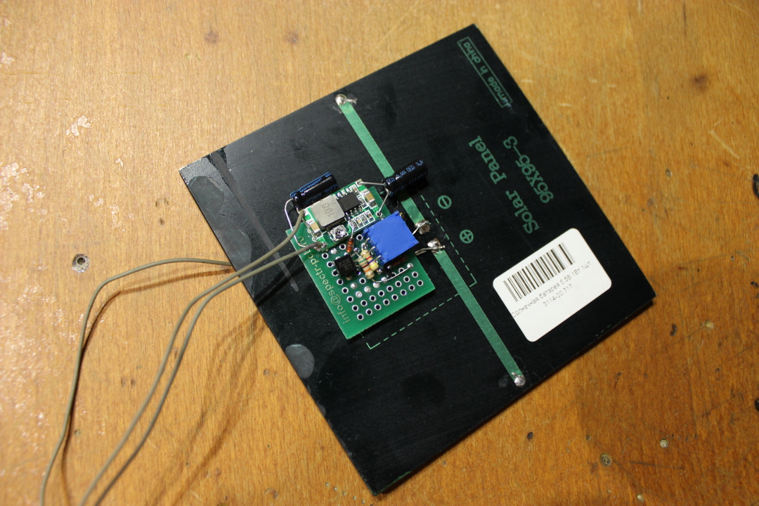
There are many types of solar cells. Conventional, familiar to all silicon elements with a bluish tint and wiring on the surface (in the photo on the left) are most effective. Their disadvantage is that they eventually collapse from sunlight, and in ten years lose most of their power.
In my book, a thin-layer element is used on copper-indium-gallium selenide (right), which is one and a half times less effective, but more durable.
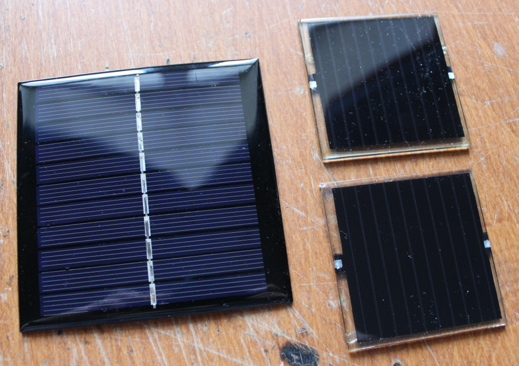 Both panels consist of 11 elements connected in series.
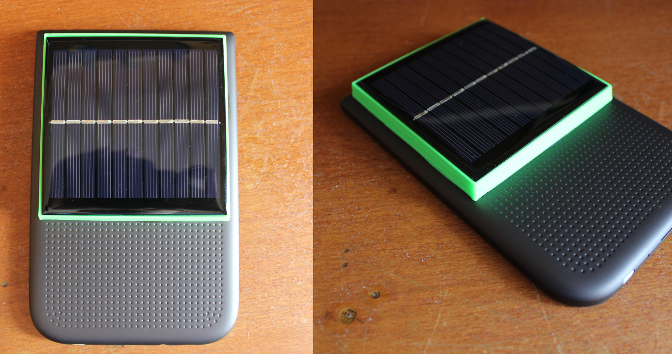
The question arises - which panel to put on our PocketBook? Usually I am for durability, but in this case the sense of beauty, driven into the far corner, required to be heard, and I stopped on the variant to the left - the typical silicon panel is painfully good for the body of the book.

Solar battery - non-linear power supply. A simple battery or power supply is usually described by Ohm's law - as the resistance applied to them decreases, the current increases and the voltage drops. In other words, they are a voltage source with equivalent series resistance.
In the case of a solar battery, with decreasing resistance, the current remains approximately constant, and the voltage drops. This is closer to the current source with a limited top voltage. Here, for example, is a graph of current to voltage for one of my large solar panels.

If you connect an ordinary battery charge controller to such a source, then charging will try to draw as much current as is available (will be a small resistance), the voltage on the panel will drop, and with it the power will drop - the full power is available only next to the working point, where the product of current and voltage is maximum.
To fix this problem, the solar panel is usually connected via a fixed power point controller. A pulse converter that does not allow the load to try to pull more power out of the panel than it can give at its optimum voltage. In fact, it converts the nonlinear characteristic of the panel into an ohmic one.
The simplest implementation of such a controller is a step-down converter with feedback also on the input voltage, and not only on the output voltage.
As the output resistance decreases, such a converter will lower the voltage (and increase the current) so that a constant voltage remains at the input.
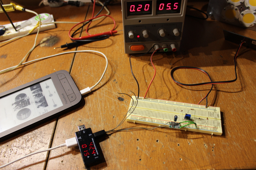
Take a look at a simple homebrew downconverter circuit on the MC34063 PWM controller.
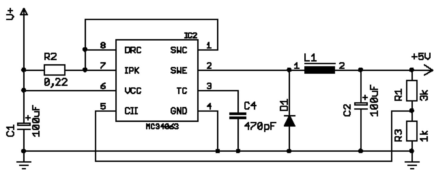
This chip has a built-in key that opens and closes with a frequency of tens of kilohertz. When it is open, the current flows through it and through the inductance, gradually gaining voltage at the output. When it is closed, the current flows through the diode and inductance (the inductor tends to resist a change in the current flowing through it), gradually losing the voltage. The resulting "triangular" voltage is smoothed by the output capacitor to close to constant.
The longer the key is open (pulse width), the higher the voltage at the output. Since Usually a constant voltage is required, the output is a feedback divider, which sends a signal to the error amplifier in the controller. This allows it to reduce the pulse width, if the voltage is too high, and increase when vice versa.
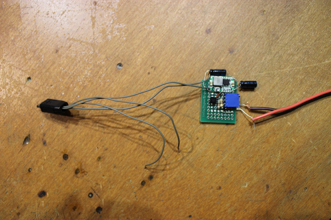
How to make a controller from this scheme with maximum power hold? It is necessary to add to it a small prefix.
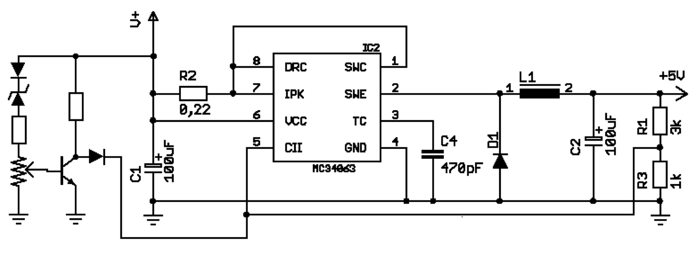 The transistor is open when the input voltage is higher than the set one, the voltage on its side of the diode is zero, and the controller limits the output voltage, as usual.If the input voltage falls below the set, then the transistor starts to close, and a voltage proportional to the input voltage falls on the feedback line. And overlaps the signal from the output. The controller perceives this as an increased voltage at the output, and reduces the pulse length, thereby preventing the load from absorbing too much power and dropping the input voltage.If we check this scheme on a breadboard, then it will be more or less working, but with rather awful characteristics.
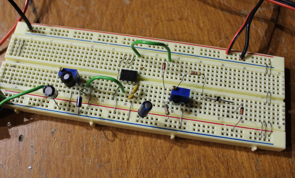
– - . , MC34063.
, . . .
– . , . , .
, .

-, .
 ,
,, .
, , , .
, – , .

- , – . .
, .

«» – 1 4000, . 29 .
« » , 6 , , 5 .
, – . , - .

- , – 0.7. – 1 70% . - 8.
– 1 1000 2. , .
, , .
. , 3D- .
, .
, .
, . – .
, , , . – , . , . , , .
- , , .

, – PocketBook — - .
, – , , , .
, , , . , . . – , , . use case .
, . , , .
, . ( 2007) , , . — - , .
PocketBook 631 Plus – , — .
Such are the cases. , , - . , .