
In this article, I will talk about how a liquid crystal indicator (LCD) works in terms of signals, how to decode these signals and use them for their own purposes.
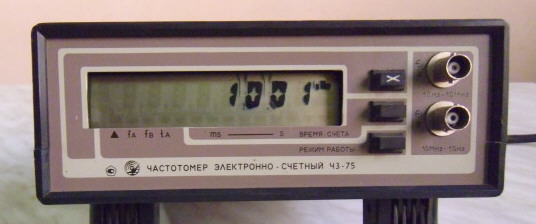
Sometimes there are questions related to the operation of the LCD. For example, the device’s screen dripped and there’s nothing to replace:
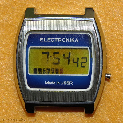
Or the LCD screen is very small, in the dark it is not visible, and the task is to convert the output instead of the LCD to an LED or other display.
I also encountered such a problem: there is an air conditioner, and to improve its performance, an additional fan must be turned on when the snowflake symbol appears on the screen.

I think you can come up with such questions a lot, and there is a common task - to learn how to decode the information displayed on the LCD, and use it for its intended purpose.
Due to their physical characteristics, liquid crystal indicators require the fulfillment of two main requirements:
- The voltage between the electrodes must be at least three volts.
- The electrodes must be supplied with alternating voltage without any constant component.
If the first requirement is not met and the voltage between the common and segment electrodes is less than 3 volts, the segment will simply not be visible.
If you do not fulfill the second requirement, the indicator can degrade rather quickly (liquid crystals will deteriorate). Indicators of the first issues were particularly hard hit by the non-fulfillment of the second requirement, and there could well be a situation when the user had forever on the indicator time when the battery was dead in the clock.
The liquid crystal display uses common and segmented electrodes. Segment electrodes are on one side of the LCD, common - on the opposite. Between them are liquid crystals. If you apply an alternating voltage, the liquid crystals will change their plane of polarization and, taking into account the polarization filters on the sides of the indicator, will not let the light through, and the segment will be displayed in black.

Here is a photo of a calculator indicator, where electrodes are visible.

As I said, an alternating voltage must be applied between the segment and common electrodes. Its frequency should be more than 30 hertz. Instead of a sinusoid, either special-shaped signals are sent, or a square wave (a square wave is a rectangular periodic signal in which the pulse duration and pause are equal), which can also be considered as a simplified sinusoid with some assumption.
The simplest LCDs have one common electrode. The number of pins in the indicator is equal to the number of segments plus the total output.
On the general conclusion is fed meander. And on the segment - also meander. The difference is that if the segment is to be displayed, then the pulse and the interval (phase, relative to the signal of the common electrode) are interchanged. If the segment is not to be displayed, then the phases are the same.

From the point of view of the indicator, when the phases coincide, the voltage between the electrodes is always 0 volts. And if the phases do not coincide, then between the electrodes the voltage is always alternating and is equal to 3 volts.
Conclusion to the indicator with one common electrode is quite simple, but if the number of segments is large, then the costs for the indicator wiring and for the reservation of the corresponding number of output ports on the controller increase accordingly.
To reduce the number of segments use two or more common electrodes. On the one hand, this significantly reduces the number of segment outputs, but on the other hand complicates the output in terms of generating signals. The idea of multiplexing signals is that one segment output is responsible for displaying two or more segments.
If in the indicator with one common signal one segment is controlled continuously, then during multiplexing the number of time intervals when one segment is controlled is divided by the number of common signals. That is, the segments with the common signal COM1 are first controlled (displayed or extinguished), the segments connected with the common signal COM2, etc., are controlled by the number of common signals in the next time interval.
Since the time intervals when one segment is controlled is shortened, the display time of the display is reduced accordingly, and the more common signals, the lower the contrast of the image as a whole.
Instead of a simple meander with several common signals, it is necessary to supply signals of a special form with intermediate voltages. Intermediate voltages are needed in order to fulfill the two requirements that I described above.
I made a small video where you can watch oscillograms from a real clock with one common electrode and a calculator with three common ones on an oscilloscope.
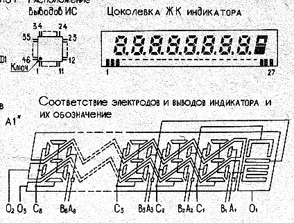
This is part of the “MK-62 Electronics” microcalculator circuit. The indicator uses three common electrodes. The diagram shows the wiring of common and segmented electrodes.
The full scheme is available
here .
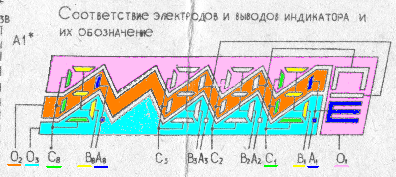
For convenience, I have colored the area of responsibility of common electrodes. In the diagram, common electrodes are designated as O1, O2, and O3.
I also painted the segmented so that it was convenient to see which segments the segment outputs are responsible for.
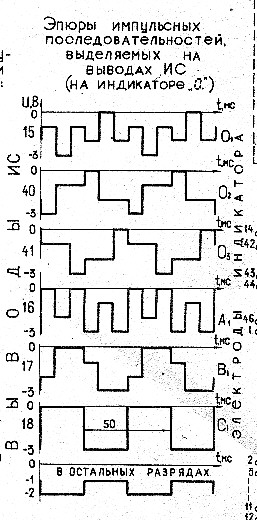
At first glance, plots of waveform signals applied to segmental and general conclusions seem creepy. But if you look at it, you can understand how it works:

The first three plots correspond to common electrodes. I colored them according to the indicator pattern on the diagram.

We will be interested only in the colored “shelves” of signals whose levels are on the tops of the oscillograms. These are the moments when segment outputs are controlled (displayed or extinguished).
In these plots it can be seen that, first, common O2 “works” below, then the shelf at O1, then at O3. After this, the shelves are the same (only at the top) first at O2, then at O1 and further - O3. So they alternate, observing the condition of alternating voltage.
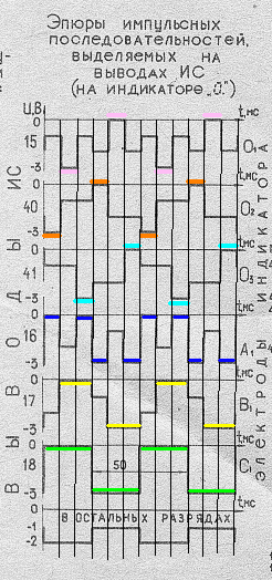
Now that the “decrypted” diagrams of the common signals can be found, you can look at the diagrams of the segment signals, which I also painted. These diagrams are from the real display on the indicator of the digit 0. (with a dot) in the first decimal place.
The pulse shape of the segmented and common signals is selected with the expectation of meeting the first requirement - the voltage between the electrodes should be three volts. Liquid crystals and polarizing filters are designed in such a way that they are displayed only at three volts, and if the voltage is lower, then the segments will not be visible.
You can independently figure out which particular segments will show or go out when the corresponding common signals arrive.
Now - after we figured out the principle of displaying segments, you can make a fairly simple decoder.
When I wrote that it is necessary to apply alternating voltage between the electrodes, this is true and correct, but only from the point of view of electrodes. Let us take advantage of the discovery of the great Einstein, which says: “everything is relative,” and become attached to one of the pole of signals (negative). All other levels will automatically become positive.
In the scheme shown above, the developers have already gone from the bipolar voltage and made signals with levels of 0 and -3 volts.
Since the logic of our device is positive, we will assume that the voltage shown in the circuit as -3 volts in our circuit will be zero, and the voltage 0 volt plus three volts.
In our scheme, when the bottom shelf arrives, it will be 0 volts (GND signal is ground). When the top shelf comes, it is +3 volts. And the remaining voltages are made to form a sinusoid, and we will ignore them.
We need to use two comparators. The comparator works simply: it has two inputs (positive and negative) and one output. When the voltage at the positive input is greater than at the negative, a unit appears at the output, and vice versa - when the voltage at the positive output is less than at the negative, then the output is zero.
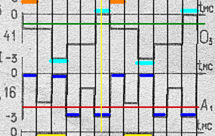
The first comparator (green line) will track the arrival of the top shelf of the common signal. The second comparator (red line) will track the arrival of the segment signal. The level of the green line is fed to the negative input of the first comparator, and the level of the red line to the negative input of the second comparator. On the positive inputs of the comparators, respectively, a common signal and a segment signal are fed. The level of the overall signal is selected at the top, and the segment level - at the bottom - in order to “catch” the moment when the segment is displayed (the same 3 volts). In other cases, it is not displayed. Pay attention to the lowest plot in the calculator circuit - those moments when the rest of the segments do not burn - there signals do not reach either the upper or the lower level.
As a result, at the time of the yellow vertical line at the outputs of the comparators, we will catch three volts of the difference between the signals when the segment is on and 0 volts when it is off.
So, we caught the moment when the desired segment is displayed (or extinguished). Now this moment must be fixed. To fix this moment, we will use a register with a latch type 74HC374. At the input of the register we give a signal from comparator No. 2, where we traced the segment signal, and to the clock input of the latch - the output from comparator No. 1, where the logical unit will start at the moment of arrival of the common signal we need.
After the register is latched on the positive jump of the CLK input, the signal at its output will not change until a new arrival of the positive shelf of the common signal we need.
To track one segment (let it be a snowflake symbol), the scheme will look like this:

Here on the diagram, the comparator U1 tracks the lower shelf of the segment signal, whose level will be lower than that set on the variable resistor RP1, and puts a zero on its output. The second comparator monitors the arrival of the upper shelf of the common signal and latches the register with a positive front.
Capacitor C1 is needed to slightly delay the detection of the general level and not fix the moment of fixation not at the very beginning of the general level (at this time the segment may be late or there will be some transient processes), but a little later (in the figure - the yellow line in the middle of the shelf). The output of the register will be a logical zero when the segment is displayed, and a logical one when the segment is not displayed.
This scheme is needed to detect each segment. The main difficulty of such a scheme is that a separate comparator is needed for each segment and common signal, and the number of register outputs is equal to the number of segments. But on the other hand, all these comparators and registers are now worth a penny.
To simplify the work and test the performance of everything I wrote, I made a small handkerchief, on which I spread out several comparators and registers.

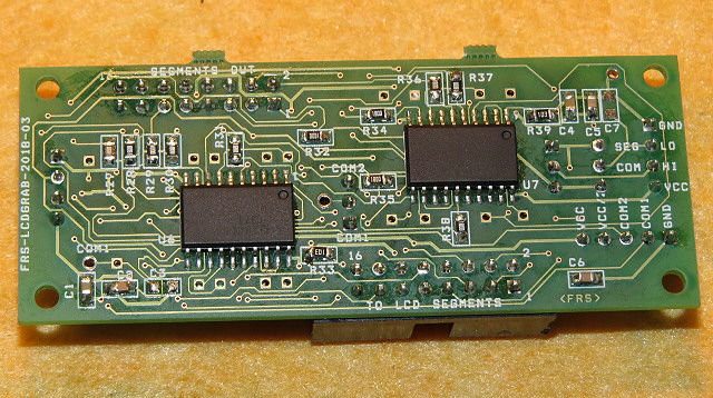
Scheme:
habrastorage.org/webt/wk/1i/kg/wk1ikgqdavyjnxcqsqlr2174jke.jpegThe description of the circuit is the same as for one segment, only multiplied by 16 segment segments and one or two common signals (the quantity is selected with a jumper).
The board provides transit inputs for power and comparators to save on details and configuration.
Here is another video that describes the operation of this board and shows how detection works:
Calculator detection is interesting only for academic purposes, and for myself, on the basis of these boards, I made a real device - an LED clock based on the Soviet Electronics 55 watch.


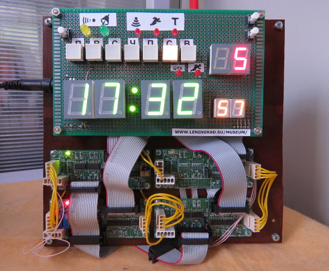
There are quite a few segments in the watch, and I had to use four boards.
These boards also allow multiplexing of register outputs. That is, the outputs of each register can be combined into one 8-bit bus. The boards provide for disabling outputs (leg 1 for each register). To disable each register, a logical unit is fed (for example, from a 74HC137 type multiplexer chip), and a logical zero is sent to the register from which it is necessary to remove data. Then, alternately selecting the desired register, you can read data from the LCD bus, for example, with another microcontroller, and then process it as you see fit. Moreover, the sample can be made asynchronously from the decoding scheme at any speed.
This is how you can read information from the LCD and use it for your own purposes. Thanks for attention.