
I continue the theme of imitation of levitation. For those who have not read the first publication, can follow the
link . Unlike the first publication, in this article I will demonstrate the pseudo-left-out analysis of air bubbles in water.
At the beginning of the video clip, all the pseudo-variations I have tested are demonstrated, and then from
3:17 minutes a brief explanation begins. Those who get tired of watching the demonstration can immediately go to the explanatory part.
This demonstration uses the same strobe, but a bit simplified, since it is without an electromagnet. Instead of an electromagnet, this time I use a pulsed, aquarium pump. Which pumps the air. The pump operates on 220V at a frequency of 50 Hz. The pump is connected through a single rectifier diode. Thus, the diode misses only positive half-periods.
To synchronize bubbles with flashes of light, the stroboscope must be tuned to any multiple of 12.5-25-50-75-100 Hz. Accordingly, if the frequency of the stroboscope increases by two or more times, the distance between the bubbles will also decrease by a multiple. In the video you can see the fragment at
57 seconds , in which the frequency is increased relative to 50Hz and the bubbles are kept at a very short distance from each other.
Strobe circuit
I use the
arduino scheme from the past project because it's easier and faster for me. And for those who want to repeat the project without arduino, they can do with a regular timer on the NE555 chip.
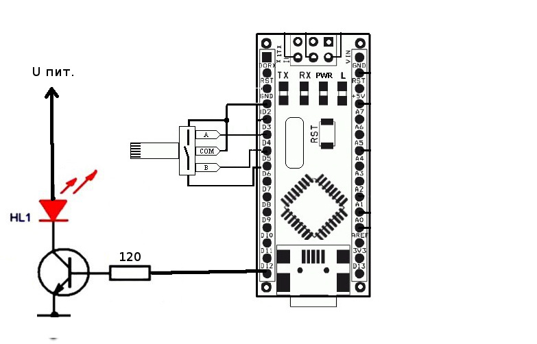
Components used in the diagram:
Arduino nano - 1 pc.
Encoder - 1 pc.
Development Board - 1 pc.
Old LED lamp - 1 pc.
Transistor KT972 - 1 pc.
Aquarium pump - 1 pc.
120 Ohm resistor - 1pc.
Explanation of the scheme:
The LED element as I said, used from the old faulty LED lamp. In which the driver did not work.
The voltage drop on the LED element found that its operating voltage is 48V. To reduce the supply voltage of the element to 24 V, I divided the element into two parts, cutting one track and paralleling these two arrays of LEDs.
Since the LED element is powered by short pulses, and the supply voltage is equal to the drop voltage on the LEDs, I did not limit the current. Because the LED element still works in an unsaturated mode.
The LED element is switched by a key on the KT972 transistor. This is a compound transistor or as it is also called the Darlington transistor, a Darlington pair. It was possible to apply MOSFET, but for such a small current and KT972 too much.
The resistor in the base of the transistor limits the output current of the controller, so that the output of the controller does not fail. According to the datasheet this current should not exceed 40mA. Rough counting, without taking into account the voltage drop at the junction of the transistor will be: 5V / 0.04A = 125 Ohm. Since there is no such nominal in the resistance line, we set 120 Ohms. If we take into account the voltage drop at the junction of the transistor, then the current will still not exceed 40mA.
The encoder operates using just one INT1 controller interrupt. At the same time there is no need to fight hardware with the bounce of contacts, as the code copes with this, without undue delay.
When the encoder rotates without pressing, the frequency changes. The default frequency in the 50Hz code. When the encoder is rotated with pressing, the duration of the strobe flash changes. The pump as I wrote above, operates on AC voltage 220V at a frequency of 50 Hz.
Strobe software
I did not edit the code from the previous project, I left everything as it is
Code for Arduino// #define CLK 3 // Clock INT1, #define DT 4 // #define SW 5 // switch #define Min 1 // #define Max 20000 // #define led_pin 12 // #define coil_pin A0 #define step_freq 1 // 0,1 #define step_timelght 100 // volatile int freq = 500; // 10, volatile uint32_t paus, time_light=2000; // uint32_t oldcount; boolean DT_last; // void setup() { pinMode(CLK,INPUT_PULLUP); // Clock INT1, pinMode(DT, INPUT_PULLUP); // pinMode(SW, INPUT_PULLUP); // pinMode(led_pin, OUTPUT); // pinMode(coil_pin, OUTPUT); attachInterrupt(1, encoderTick, CHANGE); // DT_last = digitalRead(CLK); // CLK } void loop() { paus=5000000/freq; digitalWrite(coil_pin, 1); digitalWrite(led_pin, 1); oldcount = micros(); while( (micros() - oldcount) < time_light){} // digitalWrite(led_pin, 0); while( (micros() - oldcount) < paus){} // digitalWrite(coil_pin, 0); oldcount = micros(); while( (micros() - oldcount) < paus){} // } // void encoderTick() // { uint8_t DT_now = digitalRead(CLK); // CLK if (DT_now != DT_last && digitalRead(SW)) // , { if (digitalRead(DT) != DT_now) // DT CLK, { if( freq < Max ) freq += step_freq; // } else { // DT CLK, if( freq > Min ) freq -= step_freq; // } } else if (DT_now != DT_last && !digitalRead(SW)) // { if (digitalRead(DT) != DT_now) // DT CLK, { if( time_light < paus ) { time_light += step_timelght; } // } else if( time_light > 0 ) time_light -= step_timelght; // / } DT_last = DT_now; // CLK }
I will explain how it works
A pump with a frequency of 50 Hz creates pressure in the tube, releasing in a pulse a portion of air. The dosed air in the form of bubbles, comes out of the tube with the same frequency of 50 Hz and rises up.
Having adjusted the stroboscope to the multiple frequency, the frequency of 50 Hz, we will see bubbles hanging in the water, since the frequencies will be synchronized. And the bubbles will replace each other at the inactive moment of the stroboscope. Our eye will not notice this forgery, since it captures only the illuminated scene. For physical reasons, only the reflected light can see the eye, but what does not see what is happening in the dark.
Conclusion
I hope you enjoyed this article and if you want to see new publications and not miss them, then subscribe. It is possible that in the near future I will still collect the mini rain levitating. And I will show you what I did.
If you have any questions, ask, I will answer them with pleasure.
PS
Another video that will not be included in the series of my publications, but still based on the strobe effect.