
I bring to your attention a lamp that is at the same time a visual aid "a black hole in a two-dimensional space."
Einstein's general theory of relativity states that objects with a mass distort the fabric of space-time. Black holes are points of such enormous density that the space-time in them is distorted sufficiently so that neither radiation nor matter can escape to the outside.
To recreate this phenomenon, I took a piece of black elastane to imitate the “fabric of space-time”, and around it I placed a “event horizon” - a ring of white LEDs; It is worth a little closer to the "black hole" - and the light does not come out. The longer you keep the lamp on, the more the black hole will grow, absorbing matter and energy. In our model, to simulate this, elastane stretches a braided line through a copper pipe and is driven by an electric motor at the base. The brightness control simultaneously affects the speed of tension: the more light and matter enters a black hole per unit of time, the faster it grows, and vice versa. If the lamp is turned off, the engine rotates in the opposite direction, loosening the tension, which is analogous to the black hole evaporation due to Hawking radiation.
Is such an artistic representation of a black hole useful in kinetic sculpture with primitive mechanics? Probably, yes, to the same extent as the comic book "Tim and Bit" about the little men in the computer. Or modeling of any physical phenomena with circuits on operational amplifiers. If you want a more serious, though also simplified, story about black holes - this
is the video for you on the short story on YouTube.
If you wish to assemble the same lamp, prepare:
- black stretch fabric like elastane (aka spandex, lycra, etc.)
- a half-inch copper pipe (and plastic, if you are not a steampunker) and three 90-degree corner fittings
- wooden base
- braided fishing line
- spray can with black paint
- Arduino Nano
- 9 volt power supply
- homemade white LED strip, which differs from the standard one in that all the LEDs in it are simply connected in parallel
- module with two H-bridges with through-current protection L9110
- stepper motor 28BYJ
- toggle switch
- variable resistor
- wires, solder, flux, breadboard
- tools for radio installation and woodworking
Saw three pieces of pipe: two for 330 mm and one for 368 mm.
If desired, you can polish it like this:

Drill three 16-mm holes: two at an inclination of about 25 degrees from the vertical — for pipes to which you then attach the LED ring, then stepping back 25 mm from them — the central hole for the pipe through which the fishing line will pass.
Drill two more holes of appropriate diameters for the toggle switch and the variable resistor. Another hole shown in the photo of the finished device at the end of the article was drilled erroneously, you do not need to repeat it.
Print
two sets of half -rings
with black filament and glue each of them together. To print the entire ring, the author did not have enough printer table area.
Cut a square from elastane and lay on a thin ring. Make holes in the fabric for 10 screws, then, while continuing to keep it slightly stretched, cover it with a thick ring and connect the resulting “tamper-proof” with screws. Cut the elastane remaining outside.
Tie a bead to the center of a piece of elastane with a braided fishing line.

Stick on the ring around the perimeter of the LED tape. Attach the ring to the short pipes through the fittings. Solder the wires to the tape, marking them so that the polarity is clear, or taking the colored wires, and pass through one of the pipes.
Paint the base black. Also fit the long pipe. Install all pipes, toggle switch and variable resistor to the holes provided for them. Pass the line through the long pipe installed in the middle.
Connect the components according to the attached diagram.
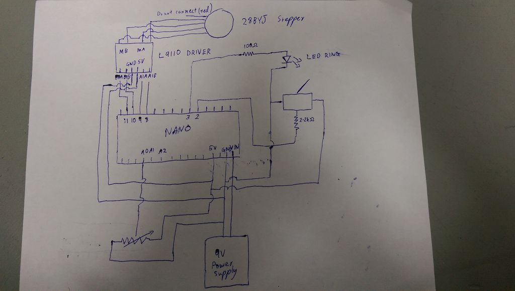
Stepper motor 28BYJ has five wires, but one of them, red, does not need to be connected anywhere. Connect the orange and pink wires to the output of the Motor B H-bridge module, and the yellow and blue wires to the Motor A output. Connect the module itself to the Arduino as follows:
B1A to D11
B1B to D10
A1A to D9
A1B to D8
The LED strip (remember, it is homemade, and all the LEDs are simply connected in parallel) connect a 100-ohm resistor between the D3 output (or another output with PWM, you can choose in the sketch) and the common wire. Connect the toggle switch so that it connects through the 2.2 kΩ resistor to the D2 input in the lower position the common wire, in the upper one the output of the five-volt stabilizer. I wonder why the author doesn’t like the pull-up resistors so much, it would allow using switches without normally closed contacts. Connect one of the side terminals of the variable resistor to the common wire, the other to the output of the five-volt stabilizer, and the middle terminal to the input A0.
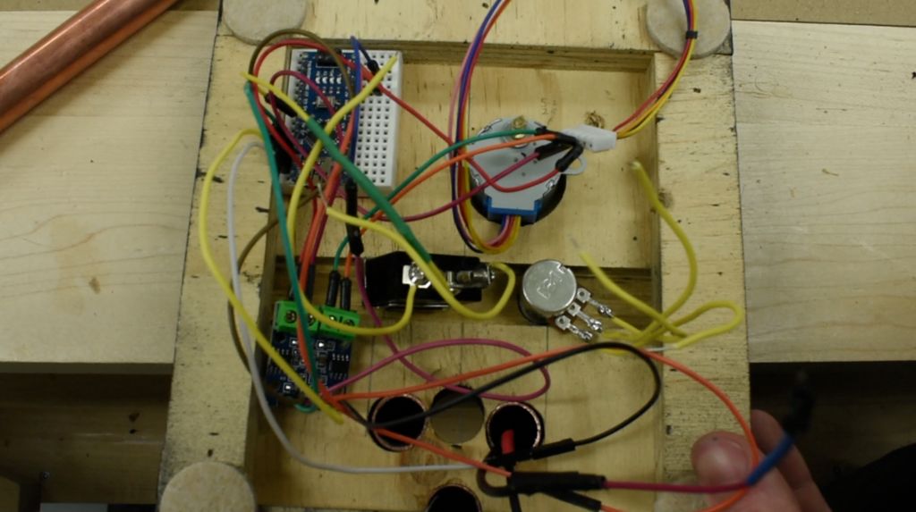
Print a pulley from the same set of STL files, put it on the motor shaft, attach the fishing line. So it turned out something like shown in the picture.
Fill the sketch:
//L9110 -> 28BYJ int A1A = 8; int A2A = 9; int B1B = 10; int B2B = 11; int PotPin = 0; // A0 int SwitchPin = 2; int LEDring = 3; // - int waitTime; // ( ) int PotVal; // int SwitchVal; int intensity; // float pulleyRadius = 1.4; // float maxStringContraction = 7.0; // , , float stepsPerRevolution = 2048.0; // float Pi = 3.14159; float circumference = 2.0 * Pi * pulleyRadius; float MaxRevs = maxStringContraction / circumference; // float MaxSteps = MaxRevs * stepsPerRevolution; // int StepLimit = MaxSteps; // int StepCount = 0; void setup() { Serial.begin(9600); //Serial.println(circumference); //Serial.println(MaxRevs); //Serial.println(MaxSteps); //Serial.println(StepLimit); pinMode(SwitchPin, INPUT); pinMode(LEDring, OUTPUT); pinMode(A1A, OUTPUT); pinMode(A2A, OUTPUT); pinMode(B1B, OUTPUT); pinMode(B2B, OUTPUT); } void step1() { digitalWrite(A1A, LOW); digitalWrite(A2A, HIGH); digitalWrite(B1B, HIGH); digitalWrite(B2B, LOW); delay(5); } void step2() { digitalWrite(A1A, LOW); digitalWrite(A2A, HIGH); digitalWrite(B1B, LOW); digitalWrite(B2B, HIGH); delay(5); } void step3() { digitalWrite(A1A, HIGH); digitalWrite(A2A, LOW); digitalWrite(B1B, LOW); digitalWrite(B2B, HIGH); delay(5); } void step4() { digitalWrite(A1A, HIGH); digitalWrite(A2A, LOW); digitalWrite(B1B, HIGH); digitalWrite(B2B, LOW); delay(5); } void Stop() { digitalWrite(A1A, LOW); digitalWrite(A2A, LOW); digitalWrite(B1B, LOW); digitalWrite(B2B, LOW); delay(5); } void BHgrowth() { analogWrite(LEDring, intensity); if (StepCount < StepLimit) { // step1(); step2(); step3(); step4(); StepCount += 1; } Stop(); } void HawkingRadiation() { analogWrite(LEDring, 0); if (StepCount > 0) { step3(); step2(); step1(); step4(); StepCount -= 1; } Stop(); } void loop() { PotVal = analogRead(PotVal); intensity = map(PotVal, 0, 1024, 0, 254); SwitchVal = digitalRead(SwitchPin); if (SwitchVal == 1) { BHgrowth(); waitTime = 255 - intensity; // , , if (waitTime < 1){ waitTime = 1; } } else { HawkingRadiation(); waitTime = 255; } delay(waitTime); Serial.println(waitTime); Serial.println(SwitchVal); }
Done, you can use!