Today, my article will be purely theoretical, or rather, there will be no “iron” in it, as in previous articles, but don't be discouraged - it has not become less useful. The fact is that the problem of protecting electronic components directly affects the reliability of devices, their resource, and therefore your important competitive advantage - the
ability to give a long-term product warranty . The implementation of protection concerns not only my favorite power electronics, but also any device in principle, so even if you design IoT crafts and you have a modest 100 mA - you still need to understand how to ensure trouble-free operation of your device.
Current protection or short circuit protection (CZ) is probably the most common type of protection because neglect in this matter has destructive consequences in the literal sense. For example, I propose to look at the voltage regulator, which was sad for the arisen short-circuit:
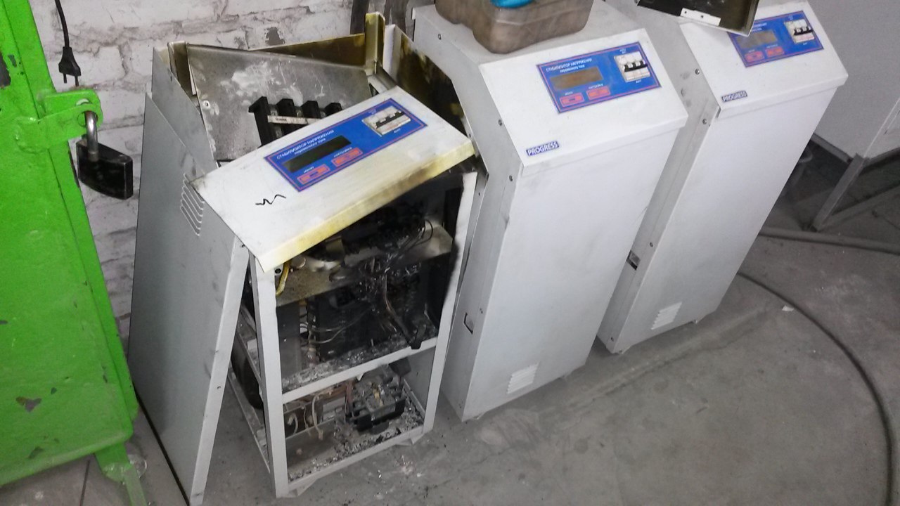
The diagnosis here is simple - an error occurred in the stabilizer and ultra high currents began to flow in the circuit, for good protection the device had to turn off the device, but something went wrong. After reading the article, it seems to me that you yourself can guess what the problem could be.
As for the load itself ... If you have an electronic device the size of a matchbox, there are no such currents, then do not think that you cannot become as sad as a stabilizer. Surely you do not want to burn bundles of chips for $ 10-1000? If so, I invite you to get acquainted with the principles and methods of dealing with short circuits!
Purpose of the article
I focus my article on people for whom electronics is a hobby and novice developers, so everything will be told “on the fingers” for a more meaningful understanding of what is happening. For those who want to be academic - go and read any university textbooks on electrical engineering + “classics” Horowitz, Hill “The Art of Circuit Engineering”.
Separately, I wanted to say that all solutions will be hardware, that is, without microcontrollers and other perversions. In recent years, it has become quite fashionable to program where necessary and not necessary. I often observe the “protection” of the current, which is realized by the banal measurement of the voltage of the ADC by some arduino or microcontroller, and then the devices still fail. I strongly advise you not to do the same! About this problem, I will tell you even further in more detail.
Little about short circuit currents
In order to start inventing protection methods, you must first understand what we are fighting with. What is a "short circuit"? Here we will be helped by Ohm's favorite law, consider the ideal case:
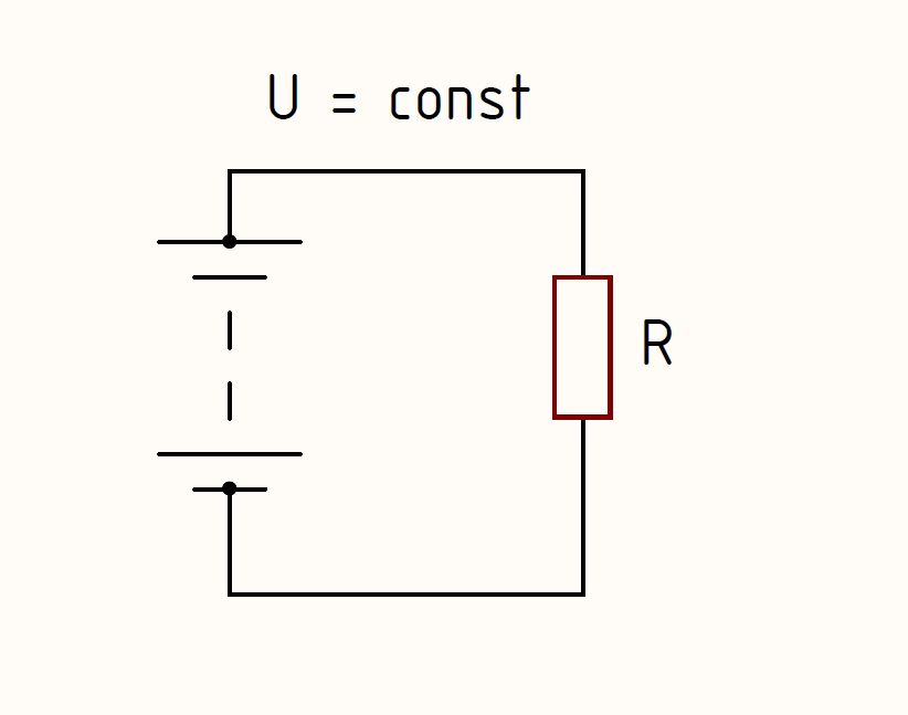
Simply? Actually, this circuit is an equivalent circuit of almost any electronic device, that is, there is a source of energy that gives it to the load, and that one heats up and does something else or does not.
Let us agree that the power of the source allows the voltage to be constant, that is, “do not sag” under any load. During normal operation, the current acting in the circuit will be equal to:
I=u/r
Now imagine that Uncle Vasya dropped a wrench on the wires going to the light bulb and our load decreased 100 times, that is, instead of R, it became 0.01 * R and with simple calculations we get a current 100 times more. If the light bulb consumes 5A, then now the current from the load will be selected around 500A, which is quite enough to melt Uncle Vasya's key. Now a small conclusion ...
Short circuit - a significant decrease in load resistance, which leads to a significant increase in current in the circuit.
It should be understood that short-circuit currents are usually hundreds and thousands of times more than the rated current, and even a short time is enough for the device to fail. Here, surely, many will remember about electromechanical protection devices (“automata” and others), but everything is very prosaic ... Usually the household outlet is protected by an automatic machine with a rated current of 16A, that is, it will turn off at 6-7 times the current, which is about 100A. The power supply of the laptop has a power of about 100 W, that is, its current is less than 1A. Even if a fault occurs, the machine will not notice this for a long time and will disconnect the load only when everything has already burned out. It is rather a fire protection, not a protection of technology.
Now let's consider another, often occurring case -
through current . I will show it on the example of a dc / dc converter with a synchronous buck topology, all MPPT controllers, many LED drivers and powerful DC / DC converters on the boards are built exactly according to it. We look at the converter circuit:
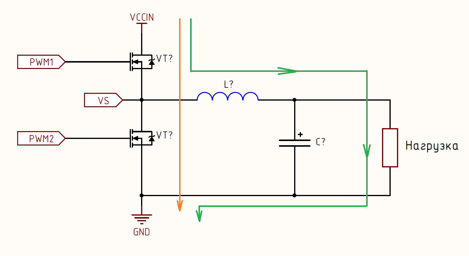
The diagram shows two options for overcurrent: the
green path for the “classical” short circuit, when the load resistance decreased (the “snot” between the soldering roads, for example) and the
orange path . When can the current flow through the orange path? I think many people know that the resistance of the open channel of the field-effect transistor is very small, in modern low-voltage transistors it is 1-10 mΩ. Now imagine that PWM with a high level came to the keys at the same time, that is, both keys opened, for the source “VCCIN - GND” this is equivalent to connecting a load with a resistance of about 2-20 mΩ! Let's apply the great and mighty Ohm's law and get even with 5V power the current value is more than 250A! Although do not worry, there will be no such current - the components and conductors on the printed circuit board will burn out earlier and break the circuit.
This error often occurs in the power supply system and especially in power electronics. It can occur for various reasons, for example, due to a control error or lengthy transients. In the latter case, even “dead time” in your converter will not save.
I think the problem is clear and many of you are familiar, now it is clear what you need to fight with and it remains only to come up with HOW. This will go further story.
The principle of current protection
Here it is necessary to apply the usual logic and see a causal relationship:
1) The main problem is the large current values in the circuit;
2) How to understand what is the current value? -> Measure it;
3) Measured and obtained the value -> Compare it with the specified valid value;
4) If you exceed the value -> Disconnect the load from the current source.
Measure current -> Find out whether the allowed current exceeded -> Disconnect the load
Absolutely any protection, not only by current, is built that way. Depending on the physical quantity for which the protection is built, different technical problems and methods for solving them will arise in the way of implementation, but the essence is unchanged.
Now I propose to go through the entire chain of protection construction and solve all the technical problems that arise. Good protection is protection that you have foreseen and it works. It means that we cannot do without modeling, I will use the popular and free
MultiSIM Blue , which is actively promoted by Mouser. You can download it there -
link . Also I will say in advance that within the framework of this article I will not delve into circuit design and fill you with unnecessary things at this stage, just know that everything will be a little more complicated in real hardware.
Current measurement
This is the first item in our chain and probably the easiest to understand. You can measure the current in a circuit in several ways and each has its own advantages and disadvantages, which one to apply specifically in your task is up to you. I will tell, based on my experience, about these very advantages and disadvantages. Some of them are “generally accepted”, and part of my worldviews, please note that as a truth I don’t even try to pretend.
1)
Current shunt . The basis of the fundamentals, “works” all on the same great and mighty Ohm's law. The easiest, cheapest, fastest and generally the most way, but with a number of drawbacks:
a)
Lack of galvanic isolation . You will have to implement it separately, for example, using a high-speed optocoupler. It is not difficult to implement, but it requires additional space on the board, dc / dc unleashed, and other components that cost money and add dimensions. Although galvanic isolation is not always necessary, of course.
b)
At high currents it accelerates global warming . As I wrote earlier, it “works” all on Ohm’s law, which means it heats and warms the atmosphere. This leads to a decrease in efficiency and the need to cool the shunt. There is a way to minimize this disadvantage - to reduce the resistance of the shunt. Unfortunately, it cannot be infinitely reduced, and in general
I would not recommend reducing it to less than 1 mΩ if you still have little experience, because there is a need to combat interference and the requirements for the PCB design stage are increased.
In my devices, I like to use these PA2512FKF7W0R002E shunts:
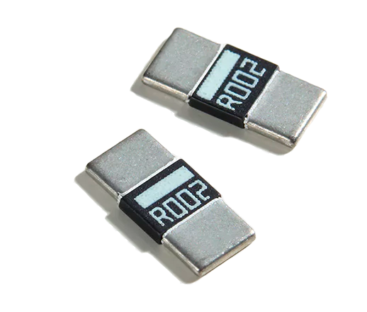
Current measurement is performed by measuring the voltage drop across the shunt, for example, when 30A current flows on the shunt there will be a drop:
Upad=I∗R=0.002Ohm∗30A=0.06V=60mV
That is, when we get a drop of 60 mV on the shunt - this will mean that we have reached the limit and if the drop increases further, then we will need to disconnect our device or load. Now let's calculate how much heat will be released on our shunt:
Pshunt=I2∗Rshunt=302∗0.002=1.8[W]
Not a little, right? This moment must be considered, since The maximum power of my shunt is 2 W and it can not be exceeded, just do not solder the shunts with low-melting solder - it can be repaired, and I have seen that.
Recommendations for use:- Use shunts when you have a high voltage and not very large currents.
- Keep track of the amount of heat generated by the shunt
- Use shunts where you need maximum speed
- Use shunts only from special materials: constantan, manganin and the like.
2)
Hall effect current sensors . Here I will allow myself my own classification, which completely reflects the essence of various decisions on this effect, namely:
cheap and
expensive .
a)
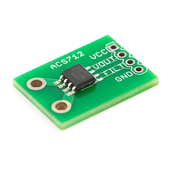
Cheap , for example, ACS712 and the like. Of the advantages, I can note the ease of use and the presence of galvanic isolation, on this the advantages end. The main disadvantage is the extremely unstable behavior under the influence of HF interference. Any dc / dc or powerful reactive load is interference, that is, in 90% of cases, these sensors are useless, because they "go crazy" and show the weather on Mars rather. But not for nothing that they do?
Do they have galvanic isolation and can measure large currents? Yes. Do not like interference? Also yes. Where to put them? Correctly, in a monitoring system with low responsibility and for measuring the current consumption from batteries. I have them in inverters for SES and WES for a qualitative assessment of the current consumption from the battery, which allows to extend the life cycle of batteries. These sensors look like this:
b)
Dear ones . They have all the advantages of cheap, but do not have their disadvantages. An example of such a sensor
LEM LTS 15-NP :
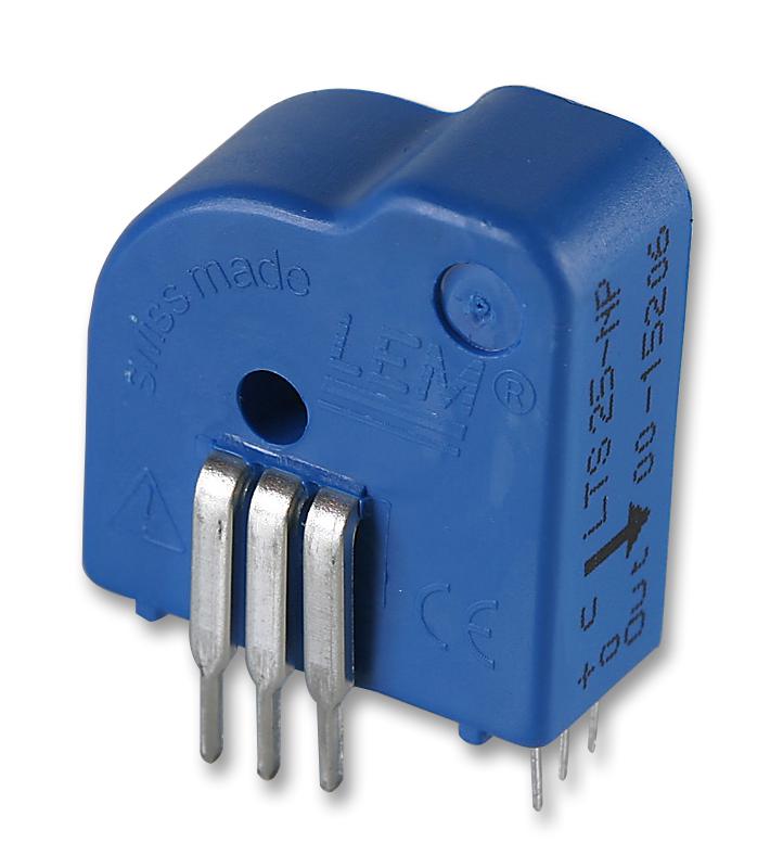 What we have in the end:
1) High speed;
2) galvanic isolation;
3) Usability;
4) Large measurable currents regardless of voltage;
5) High measurement accuracy;
6) Even the "evil" EMR do not interfere with work and not; affect accuracy.
But then what is the minus? Those who opened the link above clearly saw it - this is the price. $ 18, Carl! And even for a series of 1000+ pieces, the price will not fall below $ 10, and the actual purchase will be $ 12-13. In BP for a couple of bucks this is not put, but as we would like ...
Let's summarize:a) This is the best solution in principle for measuring current, but expensive;
b) Use these sensors in severe operating conditions;
c) Use these sensors in critical nodes;
d) Use them if your device costs a lot of money, for example, a 5-10 kW UPS, there it will definitely justify itself, because the price of the device will be several thousand $.
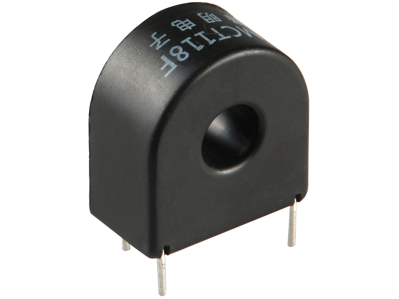
3)
Current transformer . The standard solution in many devices. Minus two - do not work with direct current and have non-linear characteristics. Pros - cheap, reliable and you can measure just huge currents. It is on the current transformers that the automation and protection systems in the RU-0.4, 6, 10, 35 kV at the enterprises are built, and there thousands of amperes are quite normal.
Honestly, I try not to use them, because I do not like them, but in various control cabinets and other systems on alternating current I still put them, because they cost a couple of dollars and give a galvanic isolation, and not $ 15-20 as LEMs and perfectly perform their task in the 50 Hz network. They usually look like this, but they also appear on all kinds of EFD cores:
Perhaps with current measurement methods can be finished. I talked about the main, but of course not all. To expand your own outlook and knowledge, I advise you to additionally at least google and look at various sensors on the same digikey.
Gain measured voltage drop
Further construction of the protection system will be based on the shunt as a current sensor. Let's build a system with a previously announced current value of 30A. On the shunt, we get a drop of 60 mV and there are 2 technical problems:
a) It is inconvenient to measure and compare a signal with an amplitude of 60 mV. ADCs usually have a measurement range of 3.3V, that is, with 12 bits of bit width, we get the quantization step:
Uquantum=Vref/212=3.3/4095=0.0008[V]=0.8[mV]
This means that in the range of 0-60 mV, which corresponds to 0-30A, we get a small number of steps:
n=Ushunt/Uquantum=60/0.8=75[steps]
We obtain that the measurement width will be only:
k=Imax/n=30/75=0.4[A/step]
It should be understood that this is an idealized figure and in reality they will be much worse, because The ADC itself has an error, especially around zero. Of course, we will not use the ADC for protection, but we will have to measure the current from the same shunt to build the control system. Here the task was to clearly explain, but this is also relevant for comparators, which, in the area of ground potential (0V usually), work very unstable, even rail-to-rail.
b) If we want to drag a signal with an amplitude of 60 mV across the board, then after 5-10 cm nothing will be left of it due to interference, and at the moment of the fault it is not necessary to rely on it, because EMR will increase further. Of course, you can hang the protection circuit right on the leg of the shunt, but we will not get rid of the first problem.
To solve these problems, we need an operational amplifier (op amp). I will not talk about how it works - the topic is excellently googled, but we will talk about critical parameters and the choice of OU. First, let's define the scheme. I said that there would be no special elegance here, so we will cover the OU with negative feedback (OOS) and obtain an amplifier with known gain factors. I will model this action in MultiSIM (the image is clickable):
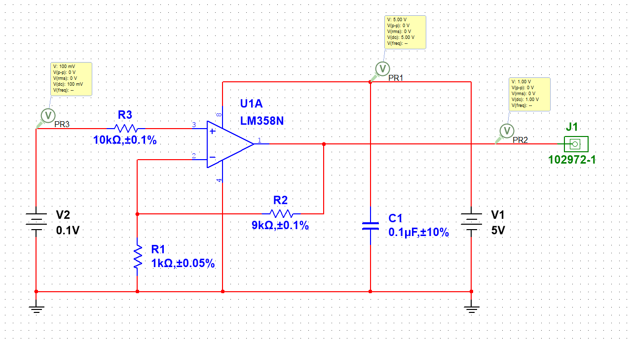
You can download the simulation file from
here -
here .
The voltage source V2 serves as our shunt, or rather, it simulates a voltage drop across it. For clarity, I chose a drop value of 100 mV, now we need to amplify the signal so as to transfer it to a more convenient voltage, usually between 1/2 and 2/3 V
ref . This will allow to get a large number of quantization steps in the range of currents + to leave a margin for measurements, in order to assess how bad everything is and calculate the time of current rise, this is important in complex reactive load control systems. The gain in this case is equal to:
Uout=Uin∗(1+ fracR2R1)=0.1∗(1+ frac91)=0.1∗10=1[V]
Thus, we have the opportunity to enhance our signal to the desired level. Now consider which parameters you should pay attention to:
- OU must be rail-to-rail to work adequately with signals near ground potential (GND)
- It is necessary to choose an op amp with a high slew rate. For my favorite OPA376, this parameter is equal to 2V / µs, which allows to reach the maximum output value of an OU equal to VCC 3.3V in just 2 µs. This speed is enough to save any converter or load with frequencies up to 200 kHz. These parameters should be understood and include the head when choosing OU, otherwise there is a chance to put OU for $ 10 where there would be enough for $ 1 amplifier
- The bandwidth selected by the OS must be at least 10 times greater than the maximum frequency switching load. Again, look for the "middle ground" in the ratio "price / TTH", everything is good in moderation
In most of my projects, I use OA from Texas Instruments - OPA376, its performance characteristics are enough to implement protection in most tasks and the price tag of $ 1 is quite good. If you need cheaper, then look at solutions from ST, and if even cheaper, then on Microchip and Micrel. For religious reasons, I use only TI and Linear, because I like it and sleep so calmly.
Add realism to the security system
Let's now in the simulator add a shunt, load, power source and other attributes that bring our model closer to reality. The result is as follows (clickable image):
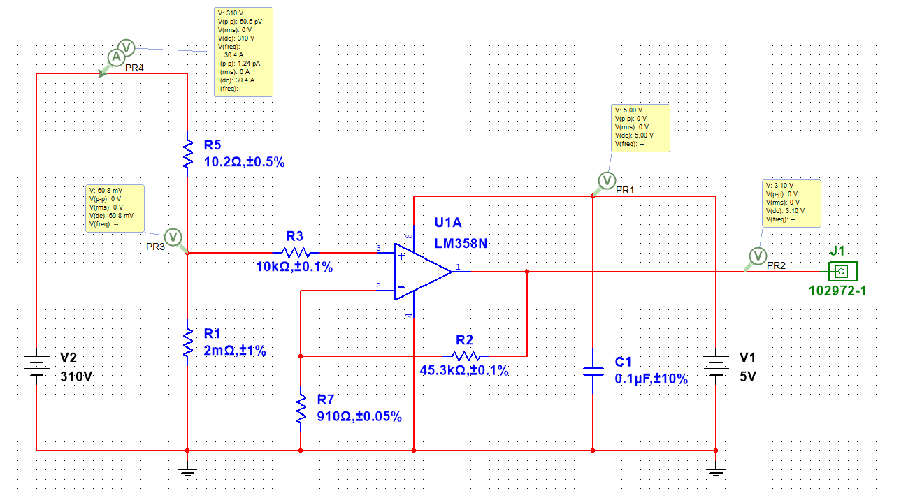
Download the simulation file for MultiSIM is possible -
here .
Here we already see our R1 shunt with the same 2 mΩ resistance, the power source I chose 310V (rectified network) and the load for it is a 10.2 ohm resistor, which again according to Ohm's law gives us a current:
I=U/R=310/10.2=30.39[A]
On the shunt, as you can see, the previously calculated 60 mV are falling and we amplify them with a gain factor:
k=1+ fracR2R7=1+ frac45300910=$50.7
At the output we get an amplified signal with an amplitude of 3.1V. Agree, it can already be sent to the ADC, and to the comparator and drag on the board 20-40 mm without any fears and deterioration of the stability of work. With this signal we will continue to work.
Comparison of signals using a comparator
A comparator is a circuit that accepts 2 signals as an input and if the signal amplitude at the direct input (+) is greater than at the inverse (-), then a log appears at the output. 1 (VCC). Otherwise, the log. 0 (GND).
Formally, any OU can be included as a comparator, but such a decision on the performance characteristics will be inferior to the comparator in speed and price / result ratio. In our case, the higher the speed, the higher the likelihood that the defense will have time to work out and save the device. I love to use a comparator, again from Texas Instrumets -
LMV7271 . What you should pay attention to:
- The response delay, in fact, is the main limiter of speed. The comparator mentioned above has a time of about 880 ns, which is quite fast and in some tasks a bit redundant at a price of $ 2 and you can choose a more optimal comparator
- Again, I advise you to use a rail-to-rail comparator, otherwise the output you will have is not 5V, but less. The simulator will help you to make sure of it, choose something not rail-to-rail and experiment. The signal from the comparator is usually fed to the driver alarm input (SD) and it would be nice to have a stable TTL signal there
- Choose a comparator with push-pull output, not open-drain and others. This is convenient and we have predicted TTX on exit.
Now let's add a comparator to our project in the simulator and look at its work in the mode when the protection did not work and the current does not exceed the alarm (clickable picture):
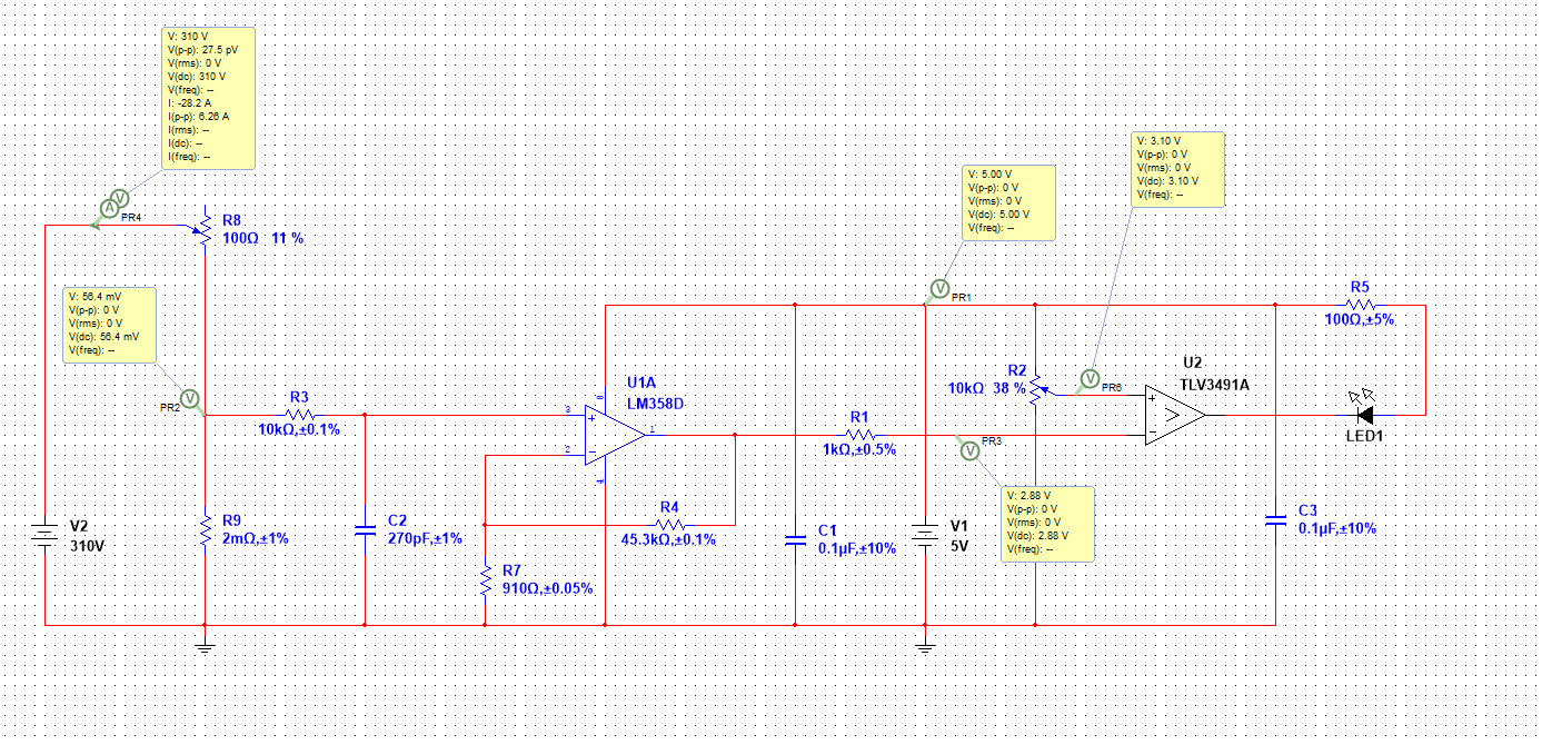
Download the file for the simulation in MultiSIM possible -
here .
What we need ... It is necessary if the current exceeds 30A, so that the output of the comparator is a log. 0 (GND), this signal will feed the SD or EN driver input and turn it off. In the normal state, the output should be a log. 1 (5V TTL) and enable the operation of the power key driver (for example, “popular” IR2110 and less ancient).
Back to our logic:1) Measured current on the shunt and received 56.4 mV;
2) Enhanced our signal with a factor of 50.78 and received at the output of the shelter 2.88V;
3) At the direct input of the comparator we send a reference signal with which we will compare. We set it with the help of the divider on R2 and expose 3.1V - this corresponds to a current of approximately 30A. This resistor controls the threshold of protection!
4) Now we give the signal from the output of the op-amp to the inverse one and compare two signals: 3.1V> 2.88V. At the direct input (+) the voltage is higher than at the inverse input (-), it means that the current is not exceeded and at the output of the log. 1 - the drivers work, and our LED1 LED is off.
Now we increase the current to a value> 30A (we twist R8 and decrease the resistance) and look at the result (clickable picture):
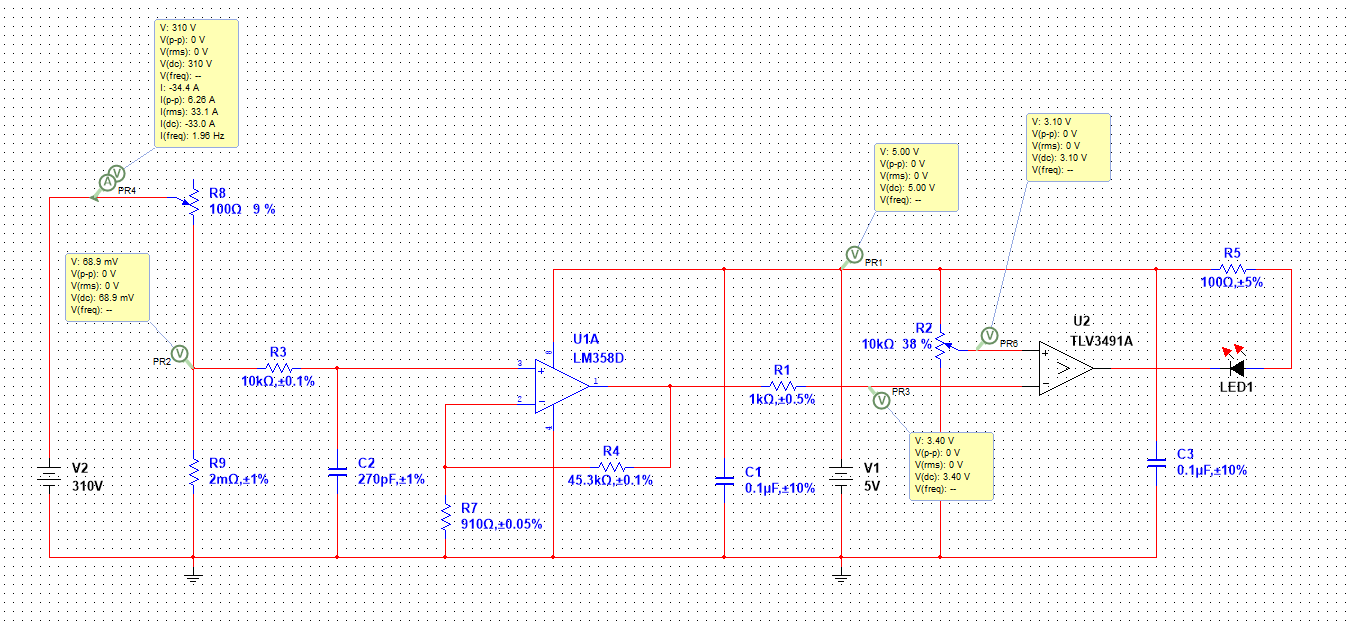
Let's review points from our “logic”:
1) Measured current on the shunt and received 68.9 mV;
2) Enhanced our signal with a factor of 50.78 and received at the output of an op-amp 3.4V;
4) Now we give the signal from the output of the op-amp to the inverse one and compare two signals: 3.1V <3.4V. At the direct input (+) the voltage is LOWER than the inverse input (-), which means that the current is exceeded and at the output of the log. 0 - the drivers do NOT work, and our LED1 LED is on.
Why hardware?
The answer to this question is simple - any programmable solution on the MK, with an external ADC, etc., can simply “hang”, and even if you are a sufficiently competent software writer and turned on the watchdog timer and other anti-freeze protection - until everything is processed your device will burn.
Hardware protection allows you to implement a system with a speed within a few microseconds, and if the budget allows, then within 100-200 ns, which is enough in general for any task. Also, hardware protection will not be able to "hang" and save the device, even if for some reason your control microcontroller or DSP is "frozen." The protection will disable the driver, your control circuit will restart quietly, test the hardware, and either give an error, for example, in Modbus or start up if everything is fine.
It is worth noting that in specialized controllers for building power converters there are special inputs that allow hardware to disable the generation of PWM signal. For example, everyone’s favorite STM32 has a BKIN input for this.
Separately, it should be said about this thing as CPLD. In fact, it is a set of high-speed logic and in terms of reliability it is comparable to a hardware solution. It is quite common sense to put on the board a small CPLD and implement in it both hardware protection, and deadtime and other amenities, if we are talking about dc / dc or some control cabinets. CPLD allows you to make this solution very flexible and convenient.
Epilogue
On this perhaps all. I hope you were interested in reading this article and she will give you some new knowledge or refresh old ones. Always try to think in advance which modules in your device should be implemented in hardware, and which in software. Often, hardware implementation is orders of magnitude simpler than software implementation, and this leads to saving time on development and, accordingly, its cost.
The format of the article without the "iron" for me is new and I will ask you to express your opinion in the survey.