This is the first (introductory) article in the series on how I am going to finalize the car’s media system. The project itself in the process, time, like everyone else - no, so, dear readers, please be patient, because I often do not promise to rivet articles.
It all started with the fact that I got a Prius.
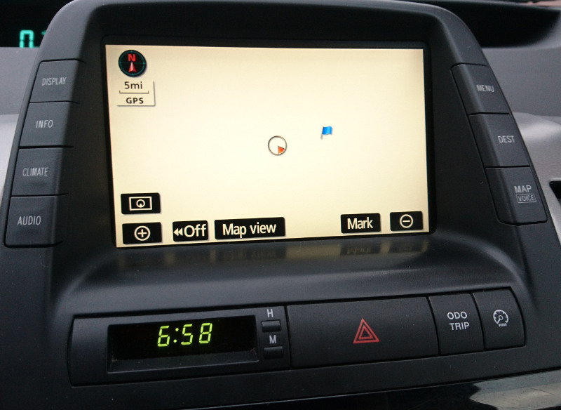
And the first thing that caught my eye - problems with updating navigation. The following are very scarce, but in some places the necessary capabilities of the device with the name “Multifunctional display” (in common people - the head). And this is against the background of a huge number of Chinese radios with Android on board, and many amenities. But their installation in a regular place implies the deprivation of such "buns" as the diagram of energy distribution and climate control.
The idea was born to somehow connect the Android radio tape recorder with the car more closely than the Chinese brothers suggest. About this article.
initial situation
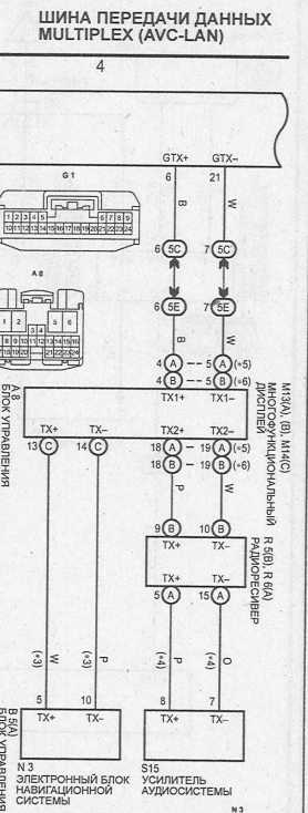
So. On board there is about a 7-inch display with a resistive touch-screen, connected to other electronics lines TX + and TX-. And these pairs from the head goes as much as 3. In the scheme, this miracle is named AVC-LAN, and looks like this:
Part 1: Looking Inside
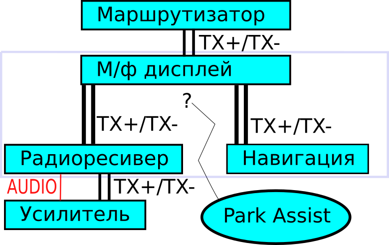
As you can see, the head stands in the network break, between the router and the further chain of the radio tape recorder, the amplifier (it is separate from me), and a separate channel is followed by communication with the navigation unit. Somewhere else, the car park unit hangs, not mentioned in the schemes I have. Well, well ... I decided to postpone intimacy with it until better times. Moreover, the parking lot - rather a game f-tion, rather than really necessary.
Removing all unnecessary, we get about the following block diagram of devices:
Reflections
It was thought to just replace the navigation unit with something android, but it faded away when I figured out more deeply how they communicate with my head. In addition to AVC-LAN, these modules are also connected by the GVIF line (Gigabit Video InterFace), and this very face of the converter manufacturers may accidentally crack if I also buy a video signal converter in GVIF for more than $ 100. "Living without a face is to be it may be difficult, but .. ”- it sounded in my head to the motive of a famous song, and I did not like the decision.
Met online solutions with the installation of the Chinese radio instead of the radio receiver. It did not suit me that the two displays - unreasonable redundancy. IMHO.
Decision
The following decision was born: to replace the whole head, and to refine the android-radio tape recorder, having made friends with it with the Prius, for which:
- Design USB <-> AVC-LAN hardware converter
- Develop firmware to it so that it connects as USB-HID.
- To make it composite, so that one of the functions is detected as a conventional hardware keyboard (with the goal of using as the native control from the buttons on the panel)
- Develop an Android application with functionality similar to (or superior) native, Priusovsky
- Negotiate the rear camera
- Solve mechanical tasks (installation in a regular place)
In the process, it presents itself to develop another application for android - an ordinary sniffer, so that it would be more convenient to reverse the packets via AVC-LAN. At the same time and practice.
It all should look like this:

As a hardware basis, it was decided to use the training board on the SM32F103:
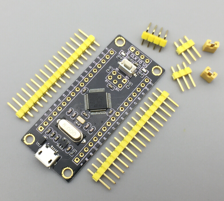
Ordered with AliExpress for $ 2.05.
Or search - spoilerPerhaps the lot has already been deleted by the seller, so I give the magic string to search for Ali:
STM32F103C8T6 ARM STM32 Minimum System Development Board Module
What I like about her:
- USB hardware module (Device) on board the processor
- Adequate USB-stack from the manufacturer (unlike Freescale-ovsky, be not remembered at night).
- Free GPIO ports that can be used to connect regular buttons on the sides of the monitor. Perhaps this will allow you to hide the radio's hardware buttons under the panel. I do not know what it will be
- And you can hang on it AVC-LAN converter to logic levels
Further I will describe in order of implementation, which is due, above all, my personal knowledge. Those. I tried to realize the places where they were not there at the very beginning, finally leaving what was surely going to happen.
In any case, several articles are planned, in different hubs. The project turns out to be very FullStack - from the hardware connection to the android application.
Part 2: USB, HID, descriptors, and everything to get a pilot prototype
The first step I wanted to get a bundle of the device and the phone, and that the device could transfer the package to the phone, and that one - to display it in the application.
As Gagarin said: Let's go!
USB HID Composite device on STM32
What I decided to take is to adapt an example from ST to my tasks and get a USB device that is recognized by the host as a composite of a keyboard and “something else” - a RAW HID Device. The first, as I said, is intended for native management of android, the second - for direct exchange of AVC-LAN packets with the program on the device.
Taking CubeMX from STM as a basis, and having read many articles on how to implement a custom HID, I found one unpleasant thing on the network: there is practically no or very poorly considered creation of composite devices.
Source codes will be laterI still do not post the source codes, due to the fact that the project is now being implemented in an experimental-educational mode. If the project is completed successfully, I will definitely drag them to Github, and edit the article with a link to it.
In the form in which they are, it makes no sense to lay out the mess - there is enough mess on the Internet without me.
USB, Composite, HID
Literally a few words on this topic. It is assumed that you are more or less familiar with the USB standard. If not, it is better to first read and experiment with examples from CubeMX.
So, we have:
STM USB stack and mouse implementation example. There we have configured some descriptors and a functional endpoint. This is in addition to a pair of 0x00 and 0x80 to control the device entirely.
To implement my project, it is required that the end point of the keyboard be bidirectional (I don’t know why it will come in handy) and another pair of end points that will be used to exchange data with the second, the RAW function. Add them.
Make the point bidirectional by adding the OUT point to the descriptor:
Configuration handleWhen editing the descriptor, keep an eye on the indices and sizes.
(2c5cf968121f0d8fa43a6755c09e15ef3a317791):
0x07, USB_DESC_TYPE_ENDPOINT, HID_EPOUT_ADDR, 0x03, HID_EPOUT_SIZE, 0x00, HID_FS_BINTERVAL,
And add a couple more points:
Configuration descriptor(bc2bd583c98715e106fcb3ab07b266bc9221be36):
0x07, USB_DESC_TYPE_ENDPOINT, HID_EPIN_ADDR2, 0x03, HID_EPIN_SIZE, 0x00, HID_FS_BINTERVAL, 0x07, USB_DESC_TYPE_ENDPOINT, HID_EPOUT_ADDR2, 0x03, HID_EPOUT_SIZE, 0x00, HID_FS_BINTERVAL,
It was a configuration descriptor. Now the host will be sure that we have some kind of composite HID device, and data can be sent to all these points. But this is not yet the case.
To make it true:
1. In our controller there is a specially selected piece of memory that is clocked with the CAN and USB modules. Given that the USB module is independently involved in the process of receiving / transmitting a data packet, it is necessary to assign it buffers in this piece of memory for each endpoint taken separately:
USBD_LL_Init in usbd_conf.c file HAL_PCDEx_PMAConfig((PCD_HandleTypeDef*)pdev->pData , 0x00 , PCD_SNG_BUF, 0x18); HAL_PCDEx_PMAConfig((PCD_HandleTypeDef*)pdev->pData , 0x80 , PCD_SNG_BUF, 0x58); HAL_PCDEx_PMAConfig((PCD_HandleTypeDef*)pdev->pData , HID_EPOUT_ADDR , PCD_SNG_BUF, 0x100); HAL_PCDEx_PMAConfig((PCD_HandleTypeDef*)pdev->pData , HID_EPIN_ADDR , PCD_SNG_BUF, 0x140); HAL_PCDEx_PMAConfig((PCD_HandleTypeDef*)pdev->pData , HID_EPOUT_ADDR2 , PCD_SNG_BUF, 0x180); HAL_PCDEx_PMAConfig((PCD_HandleTypeDef*)pdev->pData , HID_EPIN_ADDR2 , PCD_SNG_BUF, 0x1B0);
Buffer addresses are arbitrary, so as not to overlap.
For some reason, the ST stack is written on the basis that there will be no more than one bidirectional endpoint in the device, so we are slightly improving the stack:
Broadcast
The procedure USBD_HID_SendReport is renamed to USBD_HID_SendReportEP, adding one more parameter - the end point number. The procedure with the old name is left for backward compatibility, but in the body we call USBD_HID_SendReportEP with a constant in the form of an end point. The decision is not yet the most aesthetic, but it will come down for the experiment, and even if it remains - it will not interfere with a specific project.
usbd_hid.c uint8_t USBD_HID_SendReportEP (USBD_HandleTypeDef *pdev, uint8_t ep, uint8_t *report, uint16_t len) { ... , USBD_HID_SendReport } uint8_t USBD_HID_SendReport (USBD_HandleTypeDef *pdev, uint8_t *report, uint16_t len) { return USBD_HID_SendReportEP(pdev,HID_EPIN_ADDR,report,len); }
Now everything is ready for sending data, it remains only to call this function at the right moment.
Finalize
We search for the order for the project and call USBD_LL_CloseEP again, but for newly created endpoints.
Reception
In order for the end points to be morally tuned in to work, you need to call USBD_LL_PrepareReceive for them. I recommend the reader to run a search on the project for this line, and adapt these challenges to their needs.
I got this ugly cuttlefish in the code:
usbd_core.c USBD_LL_PrepareReceive(pdev, HID_EPOUT_ADDR+(epnum&0x7F)-1 , hhid->Report_buf, USBD_HID_OUTREPORT_BUF_SIZE);
Those. I proceeded from the fact that the numbers of end points go in a row. This is bad, IMHO. Do not do this. However, also as ST do not do too.
Then it remains only to go to the usbd_hid.c file, and specifically to the USBD_HID_DataOut function, and take care that the call to the received data handler matches your personal ideas of beauty. I did not really, too, so the code and description will be long and incomprehensible. Easier to do it yourself.
Report
Everything, in this place we received a composite device that is able to exchange data through two bidirectional points. The final touch is “plugging” the curiosity of the HID driver, describing such a report descriptor:
__ALIGN_BEGIN static uint8_t HID_ReportDesc2[33] __ALIGN_END = { 0x06, 0x00, 0xff,
This report says HID-driver: there will be some 31 bytes of data. No need to figure out what they are for - just give them to the program that opened this device. In the physical report, the zero byte will be equal to the report index (REPORT_ID (2)). Accordingly, a total of 32 bytes will arrive.
And enter the data about it in usbd-hid.c, function USBD_HID_Setup .:
usbd-hid.c switch (req->bRequest) { case USB_REQ_GET_DESCRIPTOR: if( req->wValue >> 8 == HID_REPORT_DESC) {
Further in the program:
- Assembly of the AVC-LAN logic level converter, and connection to the board. Analysis of the physical layer of AVC-LAN, real waveforms.
- Processing the interface at the controller level and sending packets by reports
- End-to-end interface and reverse engineering Prius. Sniffer packages (or my first Android application)
PS
- I decided to write the article because I was forced (almost) to convince me that this should be shared. Even if I do not finish the project, a certain amount of fresh information can help someone even in a “raw” form.
- Criticism of the project is welcome, because I myself still can not fully imagine that it will work out.
- Criticism of the article, design, presentation - especially since This is the first article for the resource. While continuing to work, I would like to express my thoughts in a familiar and convenient way for readers.