Good day! So it's time for the second article on the topic of ESP. I will tell you about a device that will allow you to receive information about the microclimate around your flowers (if, of course, you have them) and to receive notifications that something threatens their lives.
For what?My wife water the flowers about once a week. He looks at the soil in the pots, sees or feels that it is time for the flowers to refresh themselves and water. The flowers are different, but as it turned out they dry out in about the same time. A large pot is a big flower, a small pot is a small flower, the meaning is clear. Everything would be fine if for the summer season I did not stay at home alone for a couple of months and did not forget to water the flowers. Upon arrival in late August, his wife with a sad face pulls dry cuttings out of several pots.
It was a small digression, now about the decision. On one window sill we need 1-2 devices to make measurements in pots of different sizes. The first thing that needs to be controlled is soil moisture, something that ruins our flowers (we will not deal with the PH and the rest of the incomprehensible floristics, we don’t care). In addition to humidity, after a brief reflection, they decided to measure the illumination so that the effect of daylight on plants can be traced, the temperature and humidity of the environment - this is after.
Engineers from China have, of course, tried and made devices that can squeak and tweet when the land is dried in a pot, but still I want to have my device with its buns, especially since the cost price of the device is not so high.
Hardware implementation and job descriptionThe most important point is the autonomy of the device and the durability of its work (naturally, not at the expense of the quality of measurements). It is based on the same ESP-12E, with one ADC channel on board. The controller (module, if you wish) has several modes of operation, and, accordingly, consumption:
Power off - 0.5uA;
Deep sleep - 10uA;
Light sleep - 0.5mA;
Modem sleep - 15mA;
In the mode of data transmission up to 170mA (data vary in some sources even up to 215mA).
For our needs, we need three modes: Deep sleep, Modem sleep, and transfer mode. Since everything is so good, we will use two AAA batteries for power.
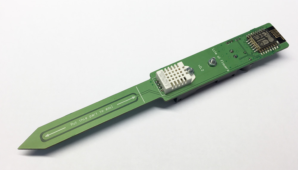
Illumination is measured by the BPW17N phototransistor, humidity and ambient temperature AM2302, soil moisture by a specially-diluted electrode on the board under the varnish. Since we have batteries, we will measure their voltage. To do this all with one ADC, we use the multiplexer CD74HC4051M96. At the ESP-12E ADC, you can apply voltage up to 1V, respectively, everywhere we put the dividers.
The scheme below, there is a lot of things for layout (there is no VT3 transistor on the soldered board, and the last one is not ready yet).
 Device layout
Two batteries provide a voltage of 3-3.3V, the multiplexer operates in the range from 2V to 6V. AM2302 operates in the range of 3.3-5.5V. ESP-12E requires voltage from 2.3V. All this is verified by tests and verified with datasheets. It becomes clear that the AM2302 will almost immediately stop working, or even not working at all, respectively, doing a "hack" and set the capacitor Buck-Boost TPS60240DGKR. This solves another serious problem, since when the voltage drops, the measured parameters float (illumination and soil moisture) and the ADC measurement values had to be corrected, taking into account the voltage, and this introduced errors.
Thus, it turns out something like this: the multiplexer is powered and controlled from the feet of the ESP (it is powered directly from the batteries), AM2302, the dividers of the light and humidity of the soil are powered from 3.3V with Buck-Boost, which, in turn, is controlled by the foot of ESP. It swings the voltage from 1.8V to 3.3V.
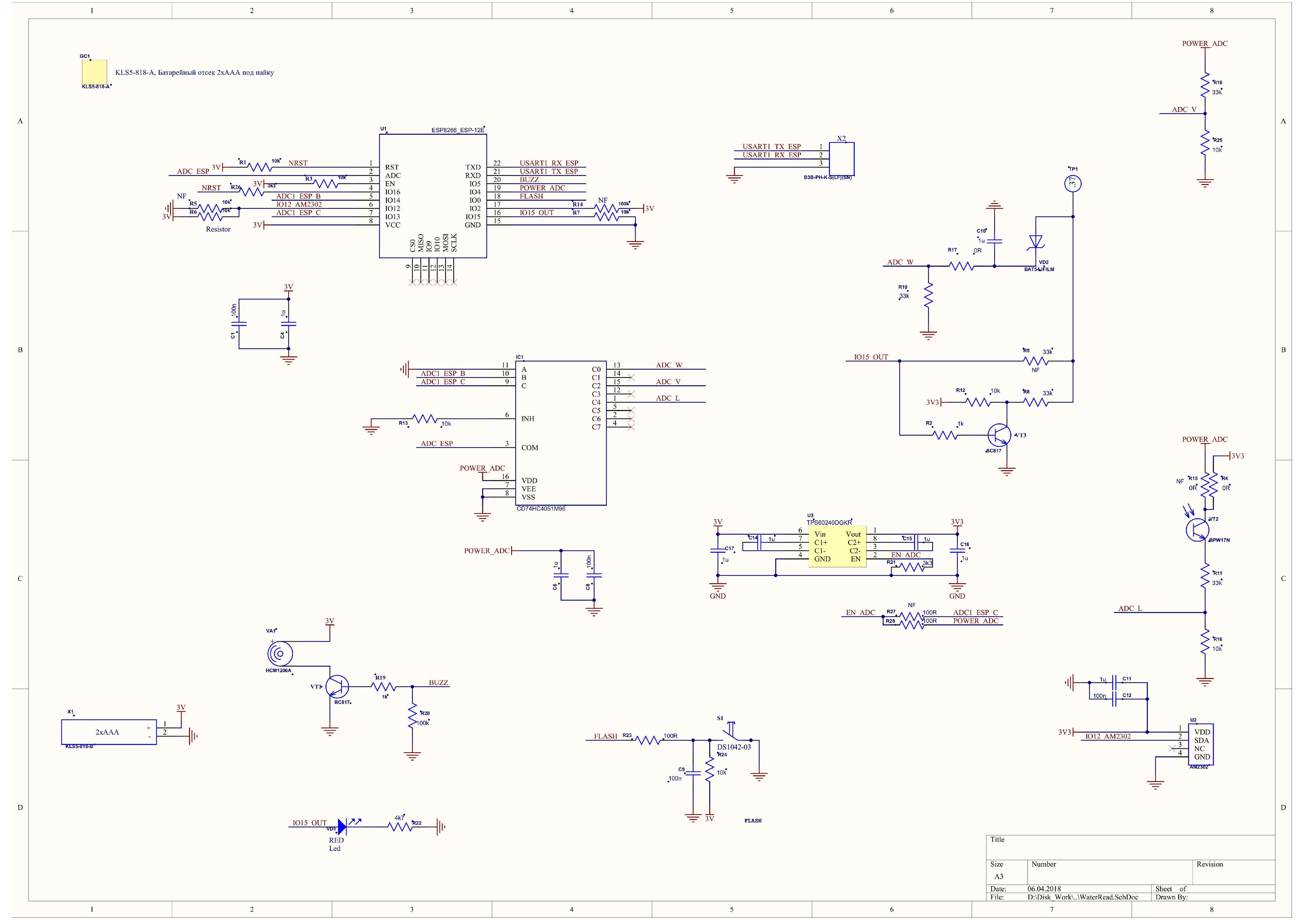
Soil moisture measurementThis value decided to take a separate subsection. The first version of the device had bare electrodes (not varnished) and everything was simple there; we applied voltage to one electrode — we removed it from the second one. The greater the humidity, the greater the voltage on the ADC.
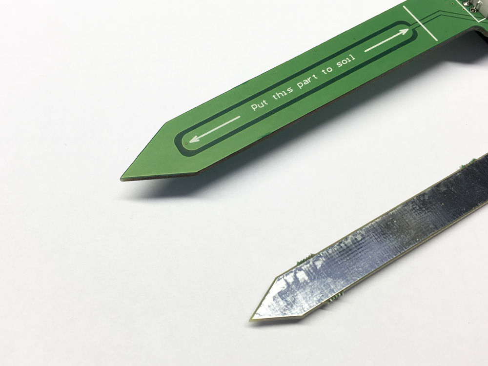 Fig 1. Electrode versions on boards.
Everything would be fine, but even tinned electrodes are prone to corrosion, and in general do not look aesthetically pleasing. Therefore, the following scheme was born (was lapped): PWM with IO15 is fed to one of the “electrodes”, and the value “rectified” and smoothed is also read from it. It turns out that the more soil moisture, the smaller the signal reaches the ADC, as the signal fades.
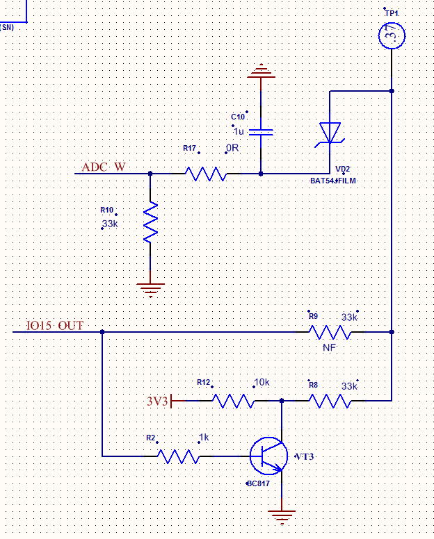 Fig 2. Scheme of reading soil moisture.Testing and work
Immediately I will clarify that the long-term tests continue, and the quick tests showed the following: the device worked (do not be in a hurry to be disappointed) for four days. Measurements were taken 1 time per minute (!!!) with sending all the data to the server (about 5700 measurements are obtained). Deep sleep is 50s from this minute. The operating time in the Modem sleep mode is a few seconds (measurements from the sensors take place), then a few seconds in the data transfer mode (tests showed a consumption of about 50mA). Time intervals are still customizable. More information about the time of work in different modes can be found on the link
here and, accordingly, see the source code on the gita
here .
While we plan to make measurements every 2 hours with a small number of measurements at night, according to estimates, we get more than 1 year of work. Calculations are more extrapolated from the obtained results, but as you know, the discharge of batteries has a nonlinear form, so long tests will show what and how.
 Fig 3. Schedules of sent parameters.
There are four parameters on one graph - it is not very convenient to look, but for that it is informative. Failure is the replacement of batteries and watering a flower. Two peaks are illumination. Blue fill is soil moisture. No smoothing and filters have been applied yet, as the testing is not finished and I want to look at the raw data. On the extended graphs, you can see how the soil is wetted, then the humidity stabilizes and slow drying occurs. They have not yet decided whether to somehow take into account the overflow of the plant or leave it to the irrigator.
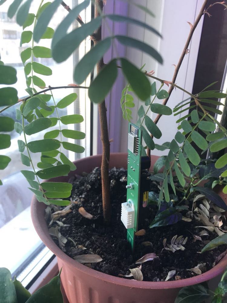 Figure 4. Photo of the device in the pot.
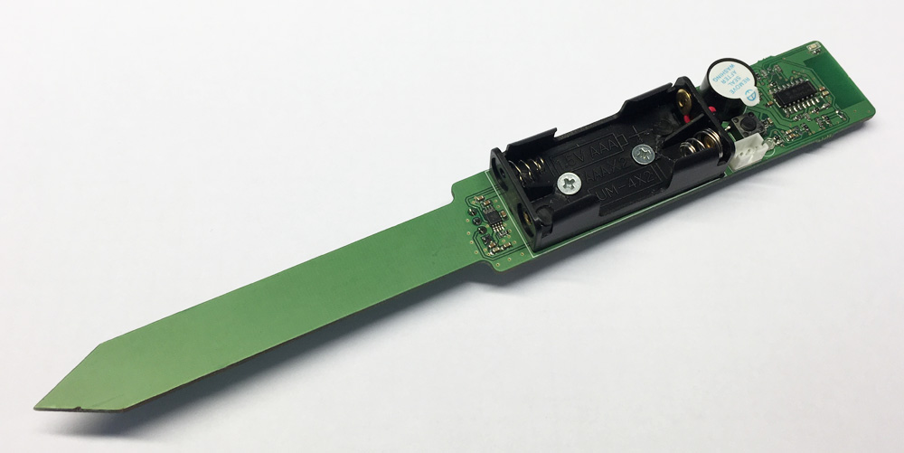 Figure 5. Photo of the device from the side of batteries.
On the model, the screws are used to fix the battery compartment and the humidity sensor, when we’ll fix everything, we put rivets, such as:
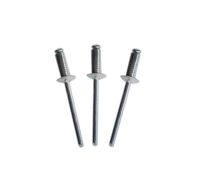 Figure 6. Photos of rivets.Housing
Everything is simple - there is no case yet, and maybe in principle, it won't be. We cover the top with a special varnish and go.
Cost priceESP-12E - 120r;
CD74HC4051M96 - 14p;
TPS60240DGKR - 180r;
BPW17N - 21p;
AM2302 - 130r;
KLS5-818-B - 15p;
BC817 - 3p;
BAT54JFILM - 3p;
Passive and button - 20p;
LED, beeper and transistor on its management while throwing out.
Without taking into account the printed circuit board and the assembly is obtained about 500 rubles.
So let's say acceptable. Of course, if you make 10pc of such devices, then the typing and assembly eats up a significant part of the cost price and the device will turn out to be expensive, but for the time being we are not chasing the price, we don’t make 100k batch, we just enjoy the process.
PlansAs mentioned earlier, in the first article, it is planned to make a family of sensors united by one application. Currently there are four devices:
1. OpenWindAir. Carbon dioxide concentration sensor.
2. LifeOfFlowers. Sensor soil moisture and microclimate for plants.
3. WarningWater. Leakage sensor
4. AirWick_ESP. Configurator for the AirWick air freshener. Probably, this is even more than a joke, I thought at first. Why not?
About this device, I have not written anything. At my house such a device was lying around:
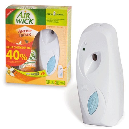 Figure 7. Photo AirWick.
And I really wanted to make it work on a schedule that I can set myself. In the daytime, for example, only when I go to the bathroom, at night, so that I can sleep at all, except that I would “pshikniku” the morning before I wake up. I even made a fee on the STM32F100, but something did not go. While I was debugging everything, changing the thresholds and the frequency of operation, everything remained in its infancy. And then the thought came, why not set the parameters from the phone, especially if this interface is already debugged:
- the number of operations after the light is turned off (depending on the time of the visit);
- the number of operations at night (the prohibition of operation when the light is on);
- turn off the device (for example, during the holidays);
- and of course, calculate how often we go to the toilet and how much time we spend there)))). When you turn on the light, my radio turns on and the visit may be delayed.
Yes - these are surpluses, you say, set up once and forgot, but our hands are not for boredom, and therefore a fee was made, which I will discuss later.
In the application for different devices, you can make tabs with the display of data and graphs related to a specific device under them.
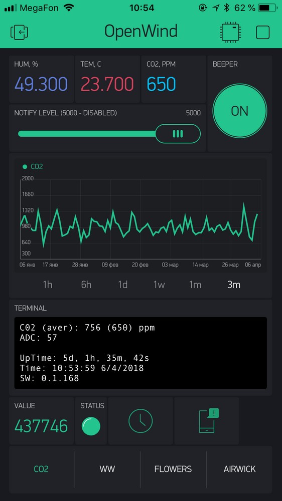 Figure 8. Photo application with multiple tabs.
PS: Links to articles from the same topic:
ESP data acquisition system. Part I. CO2Thanks for attention!