Once home automation systems, or as they are often called “smart home”, were terribly expensive and only the rich could afford them. Today on the market you can find enough budget kits with sensors, buttons / switches and actuators for controlling lighting, sockets, ventilation, water supply and other consumers. And even the
most Krivorukov DIY-Schnick can join the beautiful and inexpensively collect devices for a smart home.

Typically, the proposed device is either sensors or actuators. They make it easy to implement scenarios like “when a motion sensor trips on the light” or “a switch near the exit extinguishes the light in the whole apartment”. But with the telemetry somehow did not work out. At best, this is a graph of temperature and humidity, or instantaneous power at a particular outlet.
Recently, I set myself water meters with a pulse output. After each liter running through the meter the reed switch is activated and closes the contact. It remains the case for small - to cling to the wires and try to get from this benefit. For example, analyze water consumption by hours and days of the week. Well, if there are several risers for water in an apartment, then it is more convenient to see all current indicators on one screen than to climb hard-to-reach niches with a flashlight.
Under the cut, my version of the device based on ESP8266, which counts the impulses from the water meters and sends readings to the smart home server via MQTT. We will program in micropython using the uasyncio library. When creating the firmware, I came across some interesting difficulties, which I will also discuss in this article. Go!
Scheme
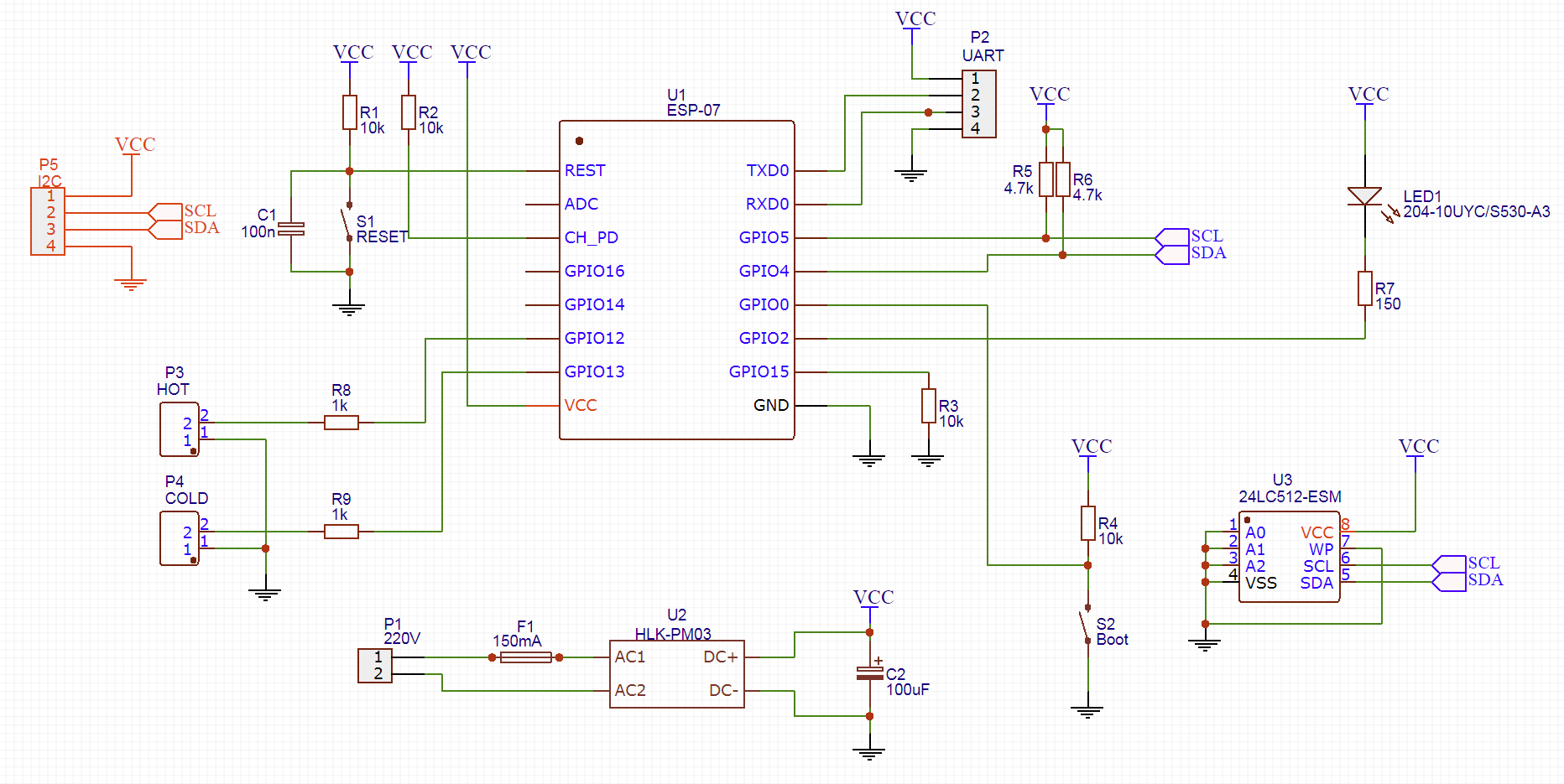
The heart of the whole circuit is the module on the ESP8266 microcontroller. Initially planned ESP-12, but mine turned out to be defective. I had to be content with the ESP-07 module that was available. Fortunately, they are the same both in conclusions and in functionality, the difference is only in the antenna - it is built-in for ESP-12, and external for ESP-07. However, even without a WiFi antenna, the signal in my bathroom is normal.
Standard module binding:
- reset button with a brace and a capacitor (although both already exist inside the module)
- Signal enable (CH_PD) pulled to power
- GPIO15 pulled to the ground. This is only needed at the start, but I still have nothing to cling to on this leg.
To transfer the module to the firmware mode, you need to close GPIO2 to the ground, and in order to be more convenient, I provided the Boot button. In normal condition, this pin pulls up to power.
The state of the GPIO2 line is checked only at the beginning of work - when power is applied or immediately after the reset. So the module is either loaded as usual, or goes into firmware mode. After downloading, this output can be used as a regular GPIO. Well, since there is already a button, then you can hang on it some useful function.
For programming and debugging, I will use the UART, which brought the comb. When needed - I just plug in a USB-UART adapter. You just need to remember that the module is powered by 3.3V. If you forget to switch the adapter to this voltage and apply 5V, then the module is likely to burn.
I have no problems with electricity in the bathroom - the socket is located about a meter from the meters, so I will power it from 220V. As a power source, I will have a small
HLK-PM03 block from Tenstar Robot. Personally, I have a hard time with analog and power electronics, and here the finished power supply is in a small package.
For signaling modes of operation, I provided an LED connected to GPIO2. However, I did not unsolder it, because In the ESP-07 module, there is already an LED, which is connected to the same GPIO2. But let it be on the board - suddenly I want to bring this LED to the case.
We turn to the most interesting. Water meters have no logic, they cannot be asked for current readings. The only thing that is available to us is the impulses - the closure of reed switch contacts every liter. The conclusions of the reed switches are set up in GPIO12 / GPIO13. I will include a pull-up resistor programmatically inside the module.
Initially, I forgot to provide resistors R8 and R9, and in my version of the board there are none. But since I already lay out the scheme for everyone to see, it is worth correcting this mistake. Resistors are needed so as not to burn the port in case the firmware of the glucanet installs the unit on the pin, and the reed switch will short-circuit this line to the ground (a maximum of 3.3V / 1000 ohm = 3.3mA will flow with a resistor).
It's time to think about what to do if electricity goes down. The first option is to start the server with the initial values of the counters at the start. But this would require a significant complication of the exchange protocol. Moreover, the operability of the device in this case depends on the state of the server. If, after turning off the light, the server did not start (or it started later), the water meter would not be able to request the initial values and would work incorrectly.
Therefore, I decided to implement the preservation of the values of the counters in the memory chip connected via I2C. I have no special requirements for the size of flash memory - you need to save only 2 numbers (the number of liters of hot and cold water meters). Even the smallest module will do. But on the number of write cycles you need to pay attention. Most modules have 100 thousand cycles, some up to a million.
It would seem that a million is a lot. But I have consumed a little more than 500 cubic meters of water in my apartment for 4 years, this is 500 thousand liters! And 500 thousand records in flash. And this is just cold water. You can, of course, solder the microcircuit every couple of years, but it turned out there are FRAM microcircuits. In terms of programming, this is the same I2C EEPROM, only with a very large number of rewrite cycles (hundreds of millions). But as long as I still can’t get to the store with such microchips, so for now the usual 24LC512 will stay.
Printed circuit board
Initially, I planned to make a fee at home. Therefore, the board was designed as one-sided. But after a good hour with a laser iron and a solder mask (without it somehow not comme il faut), I decided to order the boards from the Chinese.
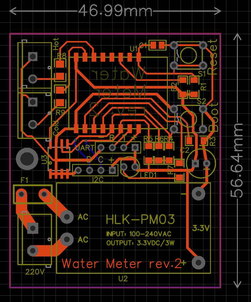
Already almost before ordering the board, I realized that in addition to the flash memory chip for the I2C bus, you can pick up something else useful, such as a display. What exactly it is to withdraw is still a question, but you need to dissolve it on the board. Well, since I was going to order the boards at the factory, then there was no point in limiting myself to a one-way board, so the lines on the I2C are the only ones on the back of the board.
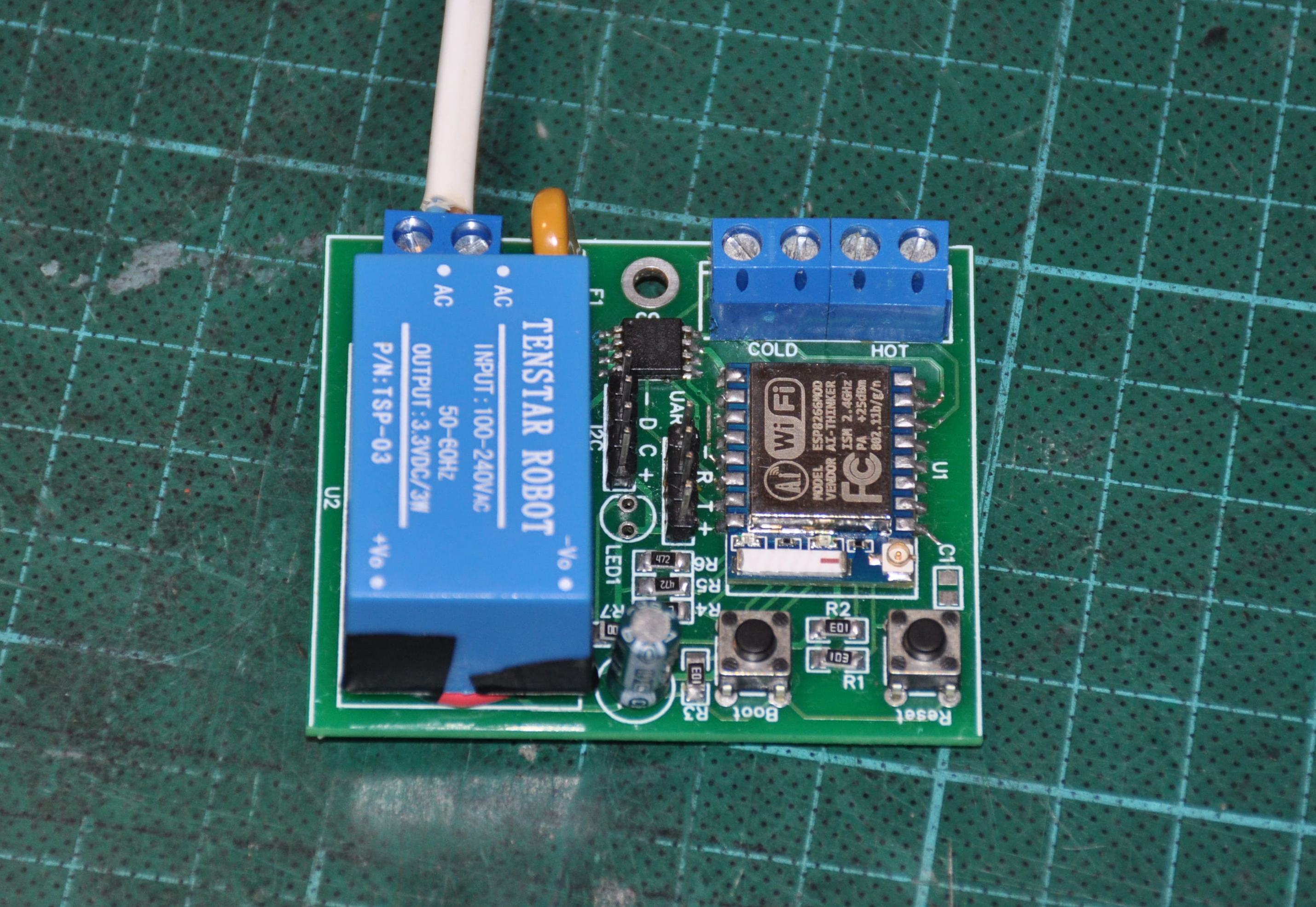
One large joint was also connected with one-sided wiring. Since If the board was drawn one-sided, it was planned to place the tracks and SMD components on one side, and the output components, connectors and power supply unit on the other. When a month later I received fees, I forgot about the original plan and unsoldered all the components on the front side. And only when it came to soldering the power supply, it turned out that plus and minus are divorced in reverse. I had to collective farm jumpers. In the picture above, I have already changed the wiring, but the ground is transferred from one part of the board to another through the findings of the Boot button (although it could be done on the second layer).
It turned out like this
Housing
The next step is the hull. With a 3D printer, this is not a problem. I didn't particularly bother - I just drew a box of the right size and made cuts in the right places. The cover is attached to the body on small screws.
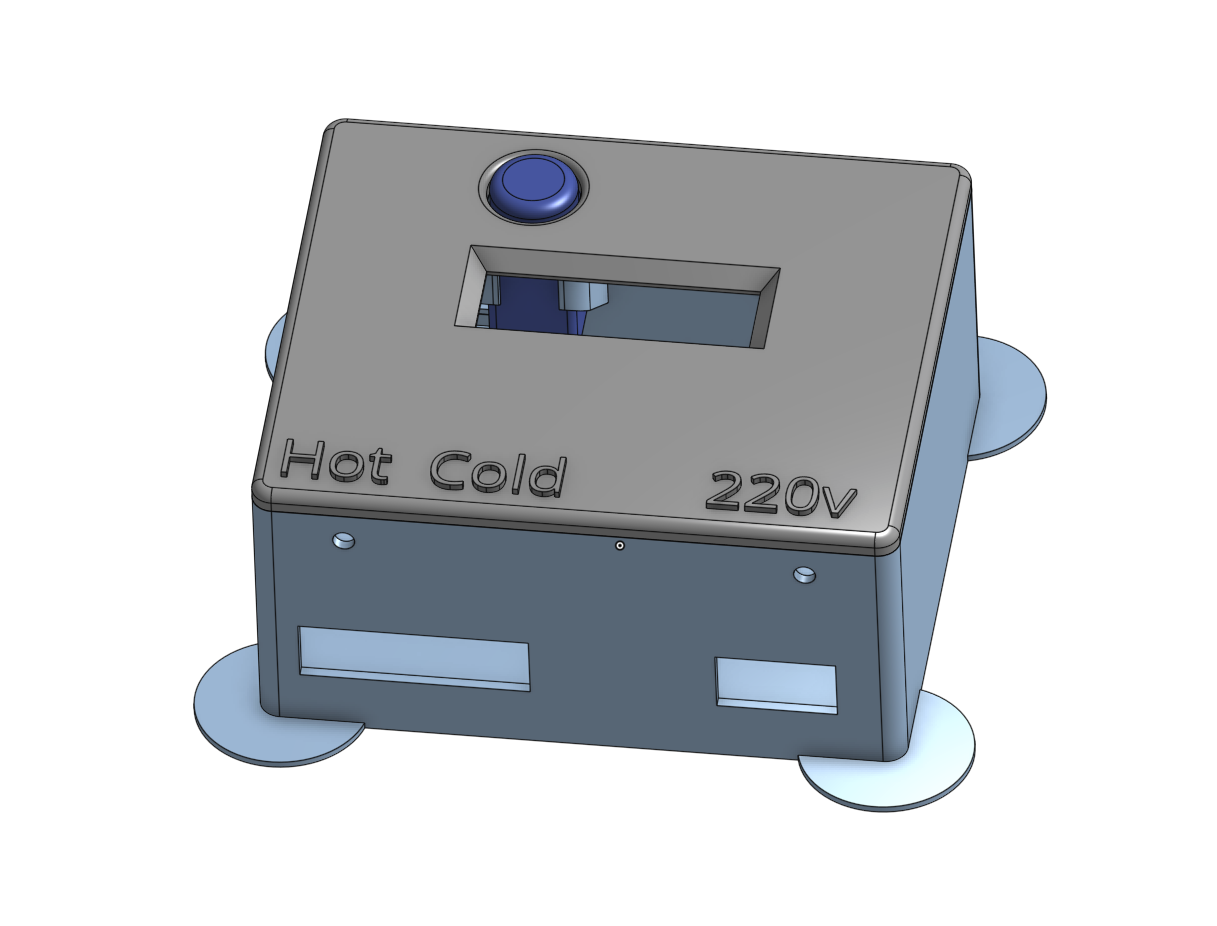
I have already mentioned that the Boot button can be used as a general-purpose button - this is what we will bring to the front panel. For this, I drew a special “well” where the button lives.
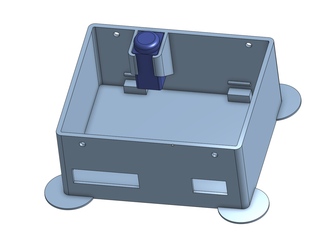
Inside the case there are also stumps on which the board is installed and fixed with a single M3 screw (there was no more space on the board)
The display was already selected when the first fitting version of the case was printed. The standard dvuhstrochnik in this case did not fit, but the OLED display SSD1306 128x32 was found in the trunk. It is small, but I don’t stare at it every day — it will roll.
Pondering this way and that, how wires will be laid from him decided to stick the display in the middle of the case. Ergonomics, of course, below the baseboard - the button on the top, the display below. But I already said that the idea to screw the display came too late and it was too lazy to re-divide the board to move the button.
Device assembly. The display module is glued to the
snot hot melt
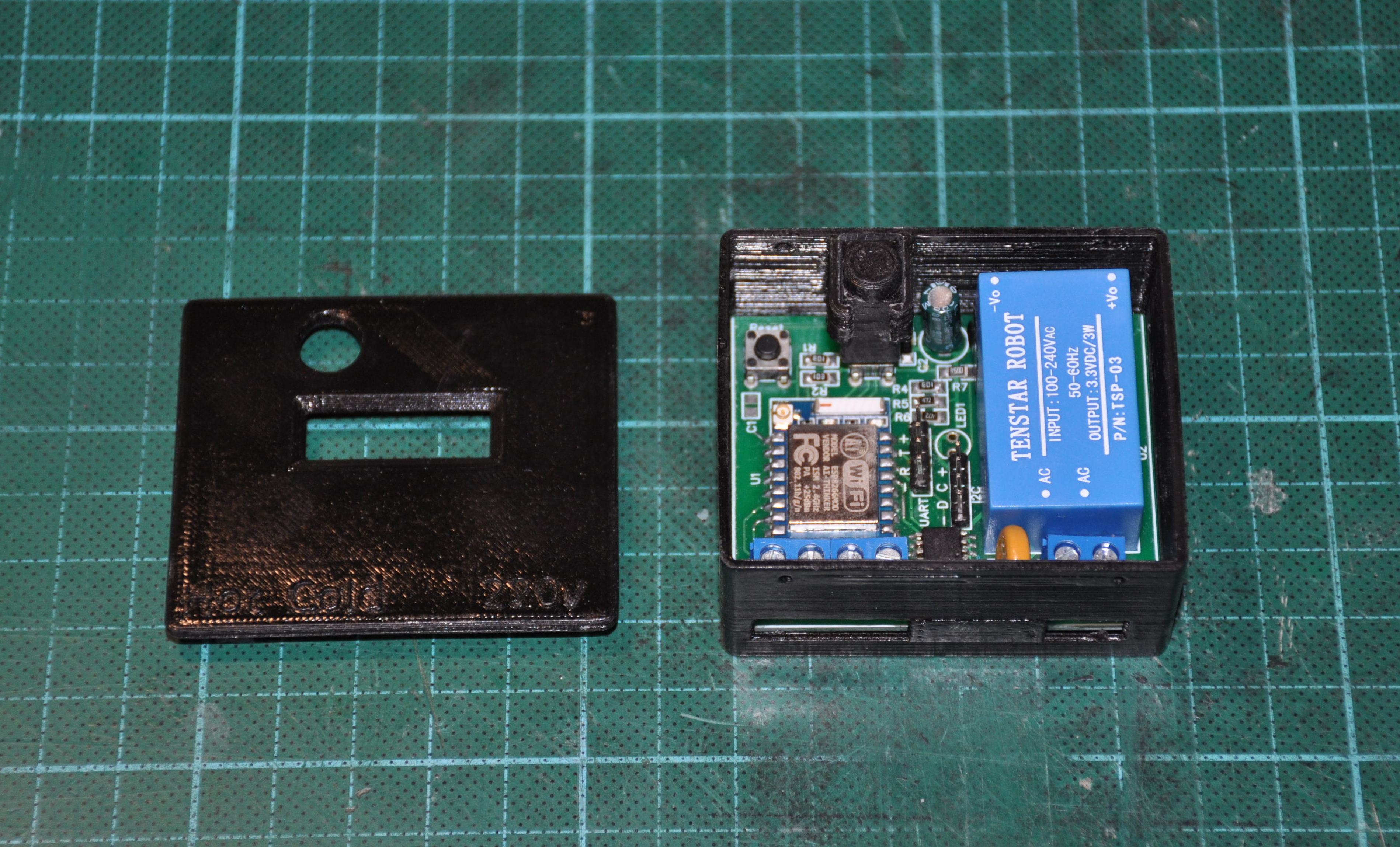
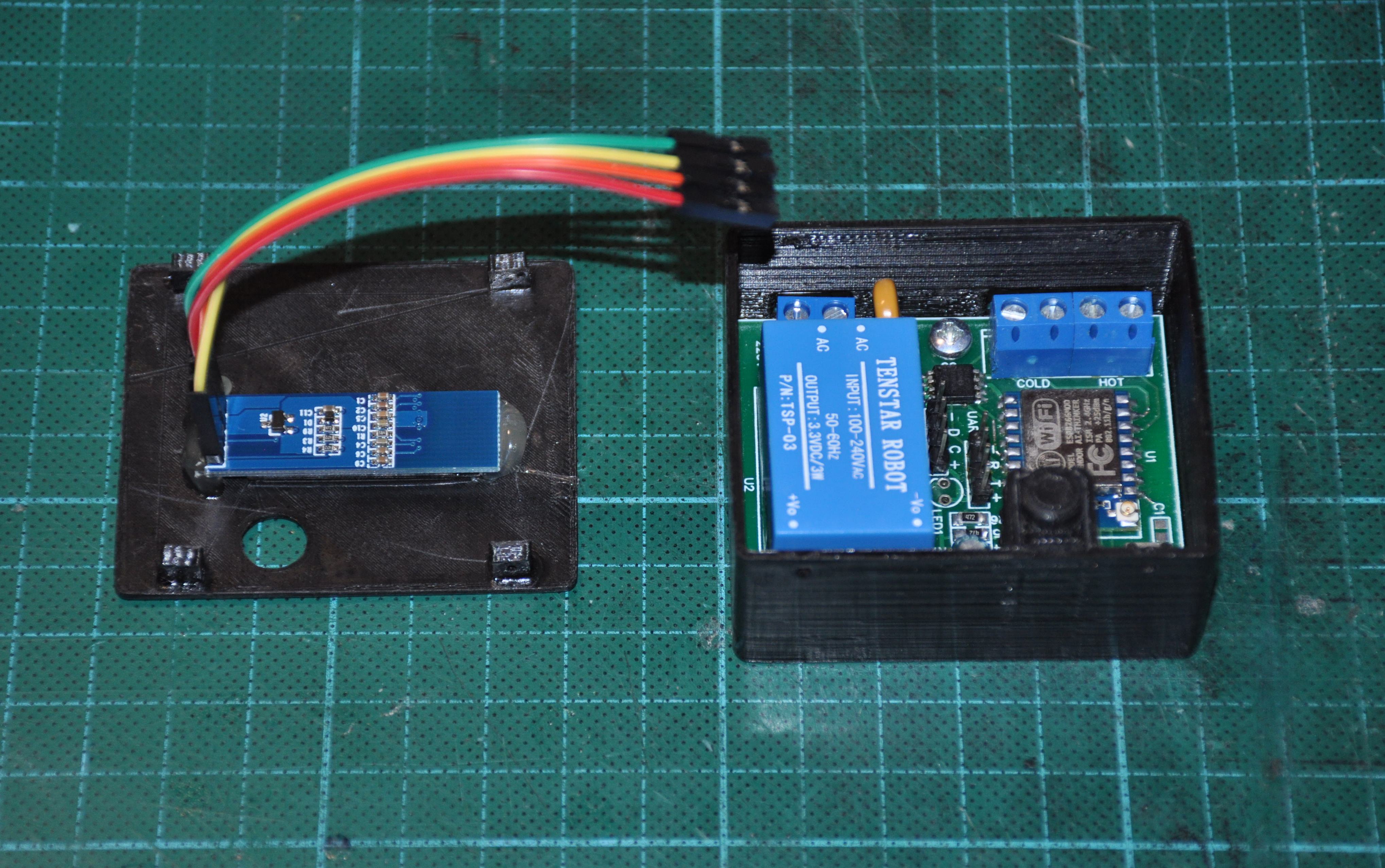
The end result can be seen on the KDPV.
Firmware
We turn to the software part. For such small handicrafts I really like to use the Python language (
micropython ) - the code is very compact and understandable. Fortunately, there is no need to go down to the level of registers in order to squeeze microseconds - everything can be done from python.
It seems to be all simple, but not very much - in the device several independent functions are planned:
- The user pokes a button and looks at the display.
- Liters tick and update values in flash memory
- The module monitors the WiFi signal and reconnects if needed.
- Well, without a blinking light bulb in general is impossible
We can not assume that one function did not work if the other for some reason tupit. I already ate cacti in other projects and now I see glitches in the style of “missed another liter, because at that moment the display was updated” or “the user cannot do anything while the module connects to WiFi”. Of course, some things can be done through interrupts, but you can rest on the restriction on the duration, nesting of calls or non-atomic change of variables. Well, the code that deals with everything and immediately turns into a mess.
In
a more serious project, I used classic preemptive multitasking and FreeRTOS, but in this case, the
coroutines model
and the uasync library turned out to be much more appropriate. Moreover, the Pythonic implementation of Korutin is just a bomb - for the programmer everything was done simply and conveniently. Just write yourself logic, just say where you can switch between threads.
The differences between preemptive and competitive multitasking I propose to explore the optional. And now let's finally move on to the code.
Each counter is processed by an instance of the class Counter. First of all, the initial value of the counter is read from the EEPROM (value_storage) - this is how the recovery after a power failure is implemented.
The pin is initialized with an integrated power lock: if the reed switch is closed, the line is zero, if the line is open, the line is pulled to the power and the controller reads the unit.
Also, a separate task is launched here that will poll the pin. Each counter will run its task. Here is her code
""" Poll pin and advance value when another litre passed """ async def _switchcheck(self): last_checked_pin_state = self._pin.value()
The delay in 25ms is needed to filter the bounce of contacts, and at the same time it regulates how often a task wakes up (while this task sleeps - other tasks work). Every 25 ms the function wakes up, checks the pin and if the reed switch contacts are closed, it means the next liter has passed through the meter and it needs to be processed.
def _another_litre_passed(self): self._value += 1 self._value_changed = True self._value_storage.write(self._value)
Processing the next liter is trivial - the counter simply increases. Well, the new value would be nice to write on a flash drive.
“Accessors” are provided for ease of use.
def value(self): self._value_changed = False return self._value def set_value(self, value): self._value = value self._value_changed = False
Well, now use the charms of the python and the uasync library and make the counter object waitable (how can this be translated into Russian? The one you can expect?)
def __await__(self): while not self._value_changed: yield from asyncio.sleep(0) return self.value() __iter__ = __await__
This is such a convenient function that waits until the counter value is updated - the function wakes up from time to time and checks the _value_changed flag. The trick of this function is that the calling code can fall asleep on the call of this function and sleep until a new value is obtained.
But what about interruptions?Yes, in this place you can potrolit, they say he said about interruptions, but in fact he made a stupid survey of pin. In fact, interrupts are the first thing I tried. In ESP8266, you can organize an interrupt on the front, and even write a handler for this interrupt on python. In this interrupt, you can update the value of a variable. Probably, this would be enough if the counter was a slave device - one that waits until it is asked for this value.
Unfortunately (or fortunately?) My device is active, it must send messages via the MQTT protocol itself and write data to the EEPROM. And here restrictions are already coming - in interrupts you cannot allocate memory and use a large stack, which means you can forget about sending messages over the network. There are bunches of the type micropython.schedule (), which allow you to run some function “as soon as right away”, but the question arises “what's the point?”. Suddenly, we are sending some message right now, and then interrupt is inserted and spoils the values of variables. Or, for example, a new counter value arrived from the server while we were still undersubscribing the old one. In general, you need to fence the synchronization or get out somehow differently.
And from time to time, RuntimeError crashes: schedule stack full and who knows why?
With an explicit survey and uasync, in this case it is somehow more beautiful and safer
I rendered work with EEPROM into a small class.
class EEPROM(): i2c_addr = const(80) def __init__(self, i2c): self.i2c = i2c self.i2c_buf = bytearray(4)
In Python, it is difficult to work directly with bytes, and it is bytes that are written to memory. I had to fence conversion between integer and bytes using the ustruct library.
In order not to transfer an I2C object and a memory cell address each time, I wrapped it all in a small and convenient classic
class EEPROMValue(): def __init__(self, i2c, eeprom_addr): self._eeprom = EEPROM(i2c) self._eeprom_addr = eeprom_addr def read(self): return self._eeprom.read(self._eeprom_addr) def write(self, value): self._eeprom.write(self._eeprom_addr, value)
The I2C object itself is created with these parameters.
i2c = I2C(freq=400000, scl=Pin(5), sda=Pin(4))
We approach the most interesting - the implementation of communication with the server on the MQTT. Well, the protocol itself is not necessary to implement - on the Internet there is a
ready-made asynchronous implementation . Here we will use it.
All the most interesting collected in the class CounterMQTTClient, which is based on the library MQTTClient. Let's start with the periphery
Here the pins of the light bulb and the buttons, as well as the objects of the hot and cold water meters are created and configured.
With initialization, not everything is so trivial
def __init__(self): self.internet_outage = True self.internet_outages = 0 self.internet_outage_start = ticks_ms() with open("config.txt") as config_file: config['ssid'] = config_file.readline().rstrip() config['wifi_pw'] = config_file.readline().rstrip() config['server'] = config_file.readline().rstrip() config['client_id'] = config_file.readline().rstrip() self._mqtt_cold_water_theme = config_file.readline().rstrip() self._mqtt_hot_water_theme = config_file.readline().rstrip() self._mqtt_debug_water_theme = config_file.readline().rstrip() config['subs_cb'] = self.mqtt_msg_handler config['wifi_coro'] = self.wifi_connection_handler config['connect_coro'] = self.mqtt_connection_handler config['clean'] = False config['clean_init'] = False super().__init__(config) loop = asyncio.get_event_loop() loop.create_task(self._heartbeat()) loop.create_task(self._counter_coro(self.cold_counter, self._mqtt_cold_water_theme)) loop.create_task(self._counter_coro(self.hot_counter, self._mqtt_hot_water_theme)) loop.create_task(self._display_coro())
To set the parameters of the mqtt_as library, use a large dictionary of various settings - config. Most of the default settings suit us, but many settings need to be made explicitly. In order not to register the settings directly in the code, I store them in a text file config.txt. This allows you to change the code regardless of the settings, as well as rivet several identical devices with different parameters.
The last block of code starts several corutins to serve various functions of the system. Here, for example, Korutina, which serves the counters
async def _counter_coro(self, counter, topic):
Korutina in the cycle waits for a new counter value and as soon as it appears, sends a message using the MQTT protocol. The first piece of code sends the initial value even if the water does not flow through the meter.
The base class MQTTClient serves itself, initiates a WiFi connection itself and reconnects when the connection is lost. If there are changes in the WiFi connection status, the library informs us by calling wifi_connection_handler
async def wifi_connection_handler(self, state): self.internet_outage = not state if state: self.dprint('WiFi is up.') duration = ticks_diff(ticks_ms(), self.internet_outage_start) // 1000 await self.publish_debug_msg('ReconnectedAfter', duration) else: self.internet_outages += 1 self.internet_outage_start = ticks_ms() self.dprint('WiFi is down.') await asyncio.sleep(0)
The function honestly lapped from the examples. In this case, it considers the number of trips (internet_outages) and their duration. When the connection is restored, idle time is sent to the server.
By the way, the last sleep is needed only for the function to become asynchronous - it is called in the library via await, and only functions in the body of which have another await can be called this way.
In addition to communicating with WiFi, you also need to establish a connection with the MQTT broker (server). The library is also engaged in this, and we have the opportunity to do something useful when the connection is established.
async def mqtt_connection_handler(self, client): await client.subscribe(self._mqtt_cold_water_theme) await client.subscribe(self._mqtt_hot_water_theme)
Here we subscribe to several messages - the server now has the ability to set the current counter values by sending a corresponding message.
def mqtt_msg_handler(self, topic, msg): topicstr = str(topic, 'utf8') self.dprint("Received MQTT message topic={}, msg={}".format(topicstr, msg)) if topicstr == self._mqtt_cold_water_theme: self.cold_counter.set_value(int(msg)) if topicstr == self._mqtt_hot_water_theme: self.hot_counter.set_value(int(msg))
This function processes incoming messages, and depending on the topic (message name), the values of one of the counters are updated.
A couple of auxiliary functions
This function is engaged in sending a message if the connection is established. If there is no connection, the message is ignored.
And this is just a handy feature that generates and sends debug messages.
async def publish_debug_msg(self, subtopic, msg): await self.publish_msg("{}/{}".format(self._mqtt_debug_water_theme, subtopic), str(msg))
So much text, and we haven't blinked the LED yet. Here is
I provided 2 blink modes. If the connection is lost (or it is just being installed), the device will blink quickly. If the connection is established - the device blinks every 5 seconds. If necessary, you can implement other blinking modes.
But the LED is so, pampering. We still swung to the display.
async def _display_coro(self): display = SSD1306_I2C(128,32, i2c) while True: display.poweron() display.fill(0) display.text("COLD: {:.3f}".format(self.cold_counter.value() / 1000), 16, 4) display.text("HOT: {:.3f}".format(self.hot_counter.value() / 1000), 16, 20) display.show() await asyncio.sleep(3) display.poweroff() while self.button(): await asyncio.sleep_ms(20)
This is what I was talking about - how easy and convenient it is with the korutins. This little function describes ALL user interaction. Korutina just waits for the button to press and turns on the display for 3 seconds. The display shows the current meter readings.
There are still a couple of little things. Here is the function that this whole farm (re) runs. The main loop deals only with sending out different debug information once a minute. In general, I bring it as it is - I do not need to make any special comments.
async def main(self): while True: try: await self._connect_to_WiFi() await self._run_main_loop() except Exception as e: self.dprint('Global communication failure: ', e) await asyncio.sleep(20) async def _connect_to_WiFi(self): self.dprint('Connecting to WiFi and MQTT') sta_if = network.WLAN(network.STA_IF) sta_if.connect(config['ssid'], config['wifi_pw']) conn = False while not conn: await self.connect() conn = True self.dprint('Connected!') self.internet_outage = False async def _run_main_loop(self):
Well, a couple of settings and constants for the completeness of the description
It all starts so
client = CounterMQTTClient() loop = asyncio.get_event_loop() loop.run_until_complete(client.main())
Something with my memory has become
So, all the code is there. I flooded the files with the help of the ampy utility - it allows you to upload them to the internal (the one that is in the ESP-07 itself) flash drive and then access it from the program as to ordinary files. I also filled in the mqtt_as, uasyncio, ssd1306 and collections libraries that I use (used inside mqtt_as).
We launch and ... We receive MemoryError. And the more I tried to understand exactly where the memory was leaking, the more I arranged the debug prints, the earlier this error occurred. A short googleg led me to understand that, in principle, in a microcontroller there are, in principle, only 30kb of memory in which 65 kb of code (together with libraries) cannot fit in any way.
But there is a way out. It turns out micropython does not execute code directly from a .py file - this file is first compiled. Moreover, it compiles directly on the microcontroller, turns into bytecode, which is then stored in memory. Well, the compiler also needs a certain amount of RAM.
The trick is to save the microcontroller from resource-intensive compilation. You can compile files on a large computer, and in the microcontroller fill the already ready baytkod. To do this, you need to download the micropython firmware and build the
mpy-cross utility .
I did not write a Makefile, and manually went through and compiled all the necessary files (including libraries) like so
mpy-cross water_counter.py
It remains only to fill in the files with the .mpy extension, without forgetting to first delete the corresponding .py from the device file system.
All the development I conducted in the program (IDE?) ESPlorer. It allows you to fill scripts in the microcontroller and immediately execute them. In my case, all the logic and creation of all objects are located in the file water_counter.py (.mpy). But in order for all this to start automatically, there must also be a file at the start with the name main.py. And it should be exactly .py, and not pre-compiled .mpy. Here is its trivial content.
import water_counter
We start - everything works. But free memory is threateningly small - about 1kb. I still have plans to expand the functionality of the device, and this kilobyte is clearly not enough for me. But it turned out that there is a way out.
The point is this. Even though the files are compiled into bytecode and are on the internal file system, in fact they are still loaded into RAM and are executed from there. But it turns out micropython can perform baytkod directly from flash memory, but for this you need to embed it directly into the firmware. This is not difficult, although on my netbook it took a decent amount of time (only there I had Linux).
The algorithm is as follows:
- Download and install the ESP Open SDK . This thing compiles the compiler and libraries for programs under ESP8266. Going according to the instructions on the main page of the project (I chose the installation STANDALONE = yes)
- Download micropython sorts
- Necessary libraries should be thrown into ports / esp8266 / modules inside the micropython tree
- We assemble the firmware according to the instructions in the ports / esp8266 / README.md file
- Fill the firmware in the microcontroller (I do this on Windows with ESP8266Flasher or Python esptool programs)
Everything, now 'import ssd1306' will pick up the code directly from the firmware and the RAM will not be used for it. With this trick, I filled in only the library code in the firmware, while the main program code I run from the file system. This allows you to easily modify the program without recompiling the firmware. At the moment I have about 8.5KB of RAM. This will allow to implement quite a lot of different useful functionality in the future. Well, if the memory is not enough at all, then you can also push the main program into the firmware.
And what to do now?
Ok, the piece of iron is soldered, the firmware is written, the box is printed, the device is stuck to the wall and blinks happily with a light bulb. But so far this is all a black box (in the literal and figurative sense) and there is still little sense from it. It's time to do something with the MQTT messages that are sent to the server.
My “smart home” is spinning on
the Majordomo system . The MQTT module is either out of the box, or easily installed from the add-ons market - I don’t remember where it came from. MQTT thing is not self-sufficient - you need a so-called. A broker is a server that receives, sorts and forwards MQTT messages to clients. I use mosquitto, which (like the majordomo) is all spinning on the same netbook.
After the device at least once sends a message, the value immediately appears in the list.
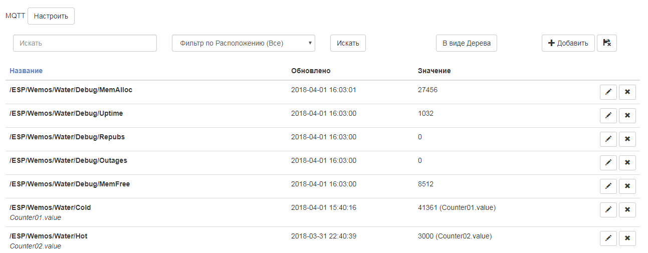
These values can now be associated with the objects of the system, they can be used in automation scripts and subjected to various analyzes - all this is out of scope of this article. Who is interested in the system majordomo I can recommend the
channel Electronics In the Objective - a friend also builds a smart home and intelligibly talks about setting up the system.
Show only a couple of graphs. This is a simple daily chart.
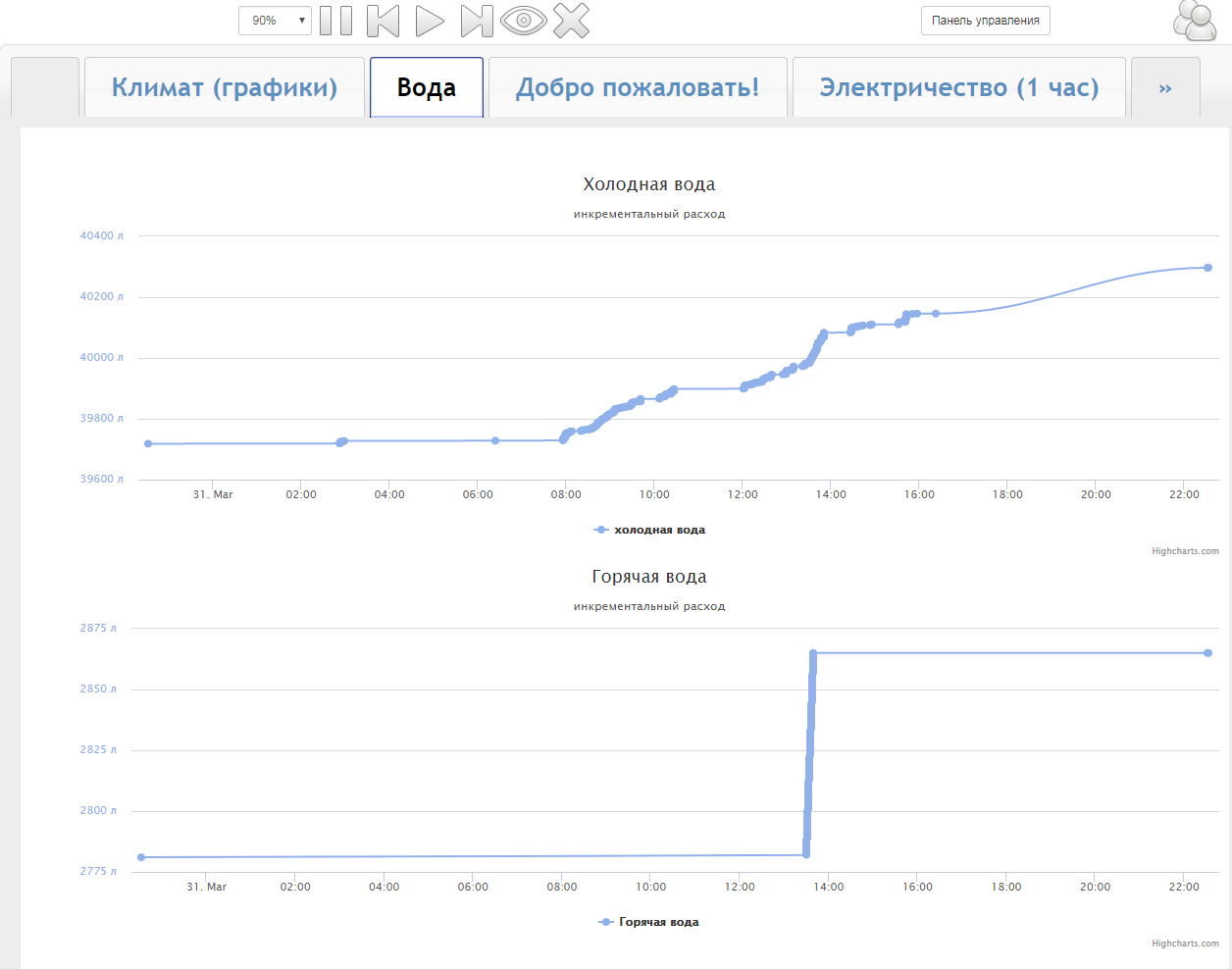
It is seen that at night almost no one used. A couple of times someone went to the toilet, and it looks like a reverse osmosis filter sucks a couple of liters per night. In the morning, consumption increases substantially. Usually I use water from the boiler, but then I wanted to take a bath and temporarily switched to the city hot water - this is also clearly visible on the lower graph.
From this chart, I learned that going to the toilet is 6-7l of water, taking a shower - 20-30l, washing the dishes around 20l, and to take a bath you need 160l. During the day my family consumes somewhere around 500-600l.
For particularly inquisitive, you can look at the records for each individual value.
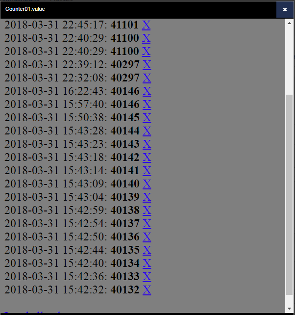
From here I learned that with the tap open, water flows at a rate of about 1 l per 5 s.
But in this form, the statistics are probably not very convenient to watch. In majordomo there are still opportunities to watch consumption graphs by day, week and month. For example, consumption graph in columns
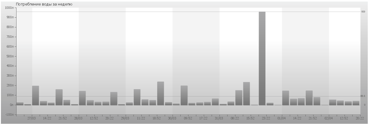
So far I have data only for a week. In a month this schedule will be more indicative - a separate bar will correspond to each day. A little picture spoil the adjustment of the values that I enter manually (the largest column). And it is not yet clear whether I incorrectly set the very first values almost a cube smaller, or whether it is a bug in the firmware and not all liters were counted. Need more time.
Above the charts themselves still need to pokolovat, whitewash, paint. Perhaps I will also be in debugging purposes to build a graph of memory consumption - suddenly something leaks there. Perhaps I will somehow display the periods when there was no Internet. While all this is spinning at the idea level.
Conclusion
Today my apartment has become a little smarter. With such a small device, it will be more convenient for me to monitor the water consumption in the house. If earlier I was indignant “again consumed a lot of water in a month”, now I can find the source of this consumption.
Someone seems strange to watch the readings on the screen, if it is a meter away from the meter itself. But in the not too distant future, I plan to move to another apartment, where there will be several water risers, and the meters themselves will most likely be located on the landing. So the remote reading device will be very helpful.
I also plan to expand the functionality of the device. I already look to the motorized valves. Now, to switch the boiler-city water, I need to turn 3 taps in a difficult niche. It would be much more convenient to do this with one button with the appropriate indication. And, of course, protection against leakage should be realized.
In the article, I told my version of the device based on ESP8266. In my opinion, I got a very interesting version of the firmware on micropython using Coroutin - simple and nice. I tried to describe the many nuances and shoals that faced the campaign. , , , .
.