If you suddenly decide for yourself that a small electric screwdriver like the Xiaomi Wowstick is simply vital, but a ready-made solution is not for you, then this article should interest you. Under the cut you expect the details of the development and instructions for making your own "bicycle". So please, gentlemen ...
The history of the creation of this device began not perfect with what I needed or wanted to have this screwdriver in my toolbox. And the process of disassembling or assembling devices with a hand screwdriver was fine with me, but the visit of my colleague at the plant changed that a bit.
One autumn day, an electrician from one of the workshops, Victor, came to our automation laboratory with a simple question to help him assemble a circuit for reversing a collector engine on small-sized relays. My colleague, Anton, got down to business, but after manufacturing, it turned out that the resulting device was larger in size than the engine itself and the battery together, to the whole, the relays were at 5 volts and started to work poorly with the battery that had run down. As a result, Victor turned to me with the question whether it was possible to somehow reduce the circuit and get rid of the relay in favor of semiconductors. I wondered what kind of final product it was for, it turned out that it should be a small electric screwdriver based on an engine purchased in China. I liked the idea, but I doubted the capabilities of the engine and asked Victor to bring it in, as they say in "live". I was a little surprised at the result I saw. The motor turned out to be quite good for its dimensions, taking into account the metal gearbox and a decent moment, at least it was not realistic to hold it with your fingers.
After a few days of thinking, I nevertheless decided that this device would be useful to me, especially the price for it is quite reasonable, and the experience of the development process is invaluable. In the end, I told Victor that I would help him make a device with much better characteristics than those that he defined for himself. Having discussed with him the main criteria for the future device, I started the development process on the same day. I introduced the general concept of the device, but it was interesting that they had already come up with it. After reviewing the ready-made solutions from manufacturers in the market and reading reviews on them, sketched out the main criteria and characteristics. What came of it, read below.
So now let's define what our screwdriver needs to meet, which would be at the level of what is on the market, and maybe a little bit better.
- overall parameters must comply with: LxWxH not more than 170x24x24 mm.
- the possibility of manufacturing the case and its components on a 3D printer.
- powered by battery size 18650.
- Charging from USB or any phone charger via micro USB connector.
- one-button on / off control.
- several rotation speeds.
- Auto shut off when idle for 5 minutes.
- indication of work and selected speed.
- without torque limiting clutch
Now that we have decided on the requirements, we can proceed with the design. For a start, let's take the case.
I looked a bit at the finished structures. I came to the conclusion that the cylinder body with a truncated cone at one end, through which the drive shaft with the bit holder goes, would be quite comfortable. It was decided to install the charging connector on the opposite end, which is convenient both when working with the connected charger cord and in terms of installing the finished charging module inside. He pondered for a long time about the location of the controls, as a result, he decided on the following configuration: the power control button is located on the side a few centimeters from the front with a charging connector. The button will be made of transparent SBS plastic or cut out of thick acrylic, which will allow it to highlight with a LED indicating the status of the device. The control buttons for the direction of rotation made closer to the edge with the drive shaft, so that it would be convenient to press them either with your thumb moving it along the buttons, or with the index and middle buttons, depending on the grip, to whom it is convenient. The mode switching button (speeds) will be located between the forward / back buttons, but on the perpendicular edge of the case. Looking ahead, it is worth saying that such a button spacing angle was not very successful, but a different solution complicated the layout of elements, but on the other hand, as practice has shown, the mode is not so often necessary to change.
The container for mounting the battery decided to make it part of the case, and the contacts will be inserted into special windows and will be slightly spring-loaded.
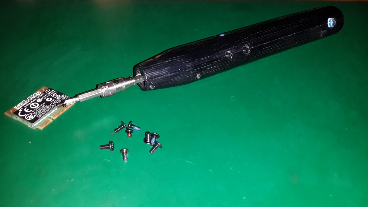
I decided to connect the drive shaft from the gearmotor to the bit holder axis through a brass coupling with 2 M3 stubs, and in addition the axis will be supported by a 623zz ball bearing, this will reduce the load on the gearbox and its mounting.
To fasten the two halves into one, 6 black screws from a set of screws for repairing a laptop were designed.
Although I own various CAD systems for design, I still got used to doing some things on paper, here and this time, before I started drawing, I sketched a sketch by hand, and then it became Autodesk Inventor.
Having made one half of the case, I downloaded the battery models, charge controller boards, gear motor and bearing created a preliminary assembly in 3D.

At first glance, everything turned out as planned. As a result, the design process took me a few days, because I did it in my free time or at lunch, but the casing was designed, followed by a long printing process on my “miracle” 3D printer ...
After 5 hours of printing and two evenings, the first copy of the case was still made of black ABS plastic. I pushers the buttons in blue for the speed switch button, black for the forward / back buttons, and the on button made of 10 mm acrylic, putting a printed ring on it to hold in the case.

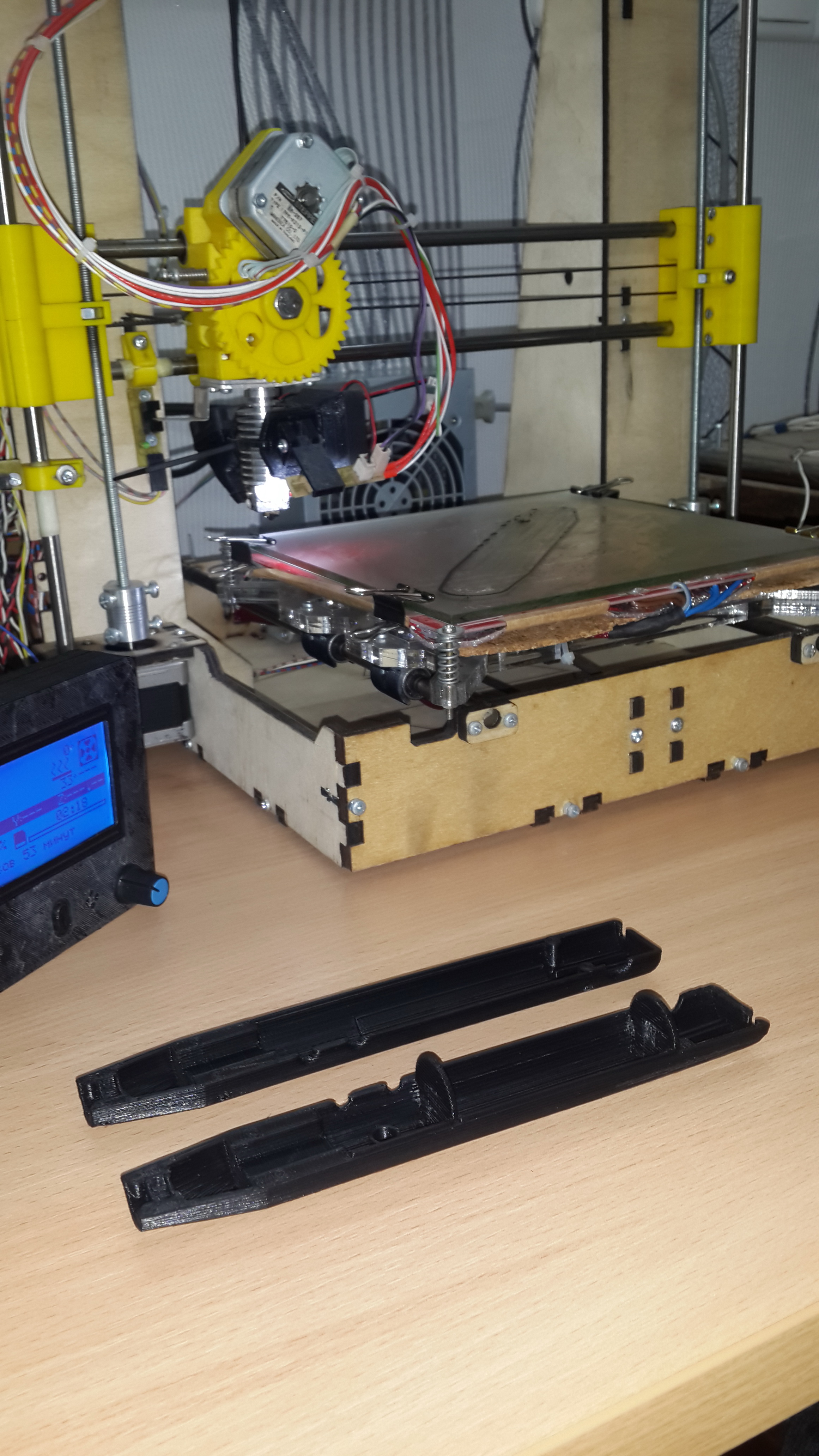
After the acetone bath and a small file processing (and where without it) all the elements fell into place without any special complaints.

The only moment is a small gap due to the fact that at the end of the first half of the printing, the model was blown up from the printing table, and it became a little crooked, but unfortunately, my printer could not do it better and I put up with it.

By the time the housing design began, the electronic control circuit was already designed and tested on a breadboard.

Structurally, I broke the circuit into 5 main nodes - this is a battery charge controller, a power management module, a boost converter, a controller, and a motor control power module (for details, see the diagram in the repository listed at the end of the article).
Here's a video of the debugging process (I apologize for the quality, but when I shot the video, I didn’t think at all that I would write an article on this topic):
A charge controller with integrated protection based on TP4056 was taken ready. This is a convenient and compact solution with indication of the charge process.
The control of one button was built on transistors based on one of the American patents, and to be precise, it was honestly borrowed from an article on
easyelectronics.ruThis scheme has been repeatedly applied by me, moreover, it has been assembled separately on my board, so that I can connect it to any project at the debugging stage. In addition to the button, the controller can also power off.
Since the engine is designed to work from 6V, and therefore at this level of supply voltage to provide the nominal torque and speed on the shaft, I decided to add a boost converter to the circuit. Well, where necessary 6B, you can make and 8B. This decision allowed to slightly raise the speed, and accordingly the moment. It also became possible to adjust the speed in a larger range with acceptable rotation characteristics. As a result, I didn’t think over the scheme for a long time, the ready-made converter on MT3608 was at hand. After measuring and testing, I came to the conclusion that it was more than enough to operate the device. In the finished circuit, all the components remained except the resistive divider in the feedback, I counted it on the voltage of 8.5 volts. Transducer components were placed on the back of the power board.
Atmel, now Microchip, ATTiny 13A, was chosen as the “brain” of the system, its resources are more than enough to accomplish the tasks, the built-in ADC allowed us to process the buttons, and the PWM controller to control the motor speed without using processor resources. In addition, it can be replaced with a more powerful AtTiny45 or similar, because they are pin-to-pin compatible.
For switching the motor, several variations of the solution were considered from the creation of an H-bridge on discrete elements to a ready-made solution based on microcircuits. As a result, he stopped at the ready in the form of a chip driver collector engine. There was a choice between the MX612 and DRV8837. After studying the manuals, I liked the driver from TI more, but the chip case did not allow making the motherboard at home without a mask, as a result I had to use the MX612. Parts were ordered in heaven (sadly, but out of 6 ordered by workers, only 3 turned out to be). As it turned out, it was possible to take the L9110S, but I apparently did little search ...
After the final inspection of the case, the boards for the controller, buttons and power management system were separated.

It now remains to deal with the mechanics. A ready gear motor with a rotational speed of 400 rpm was chosen as the engine. When ordering from the Chinese, you can ask the seller and he will make you almost any gear ratio on the gearbox. As it turned out in practice, it is better to put the engine at a lower speed, because the moment is still too small. The bearing was purchased on the market, and the coupling was ordered by a turner. An extension cord from the 4 mm bit set was taken as the bit holder. His shank was machined to 3.05 mm, so that he would sit in the tension in the bearing.
Since not everyone has the opportunity to order parts with turners, I had an idea to print a clutch. Those. we make the coupling on one side with a flat face under the output shaft of the engine, and on the other side with a hexagon under the bit holder, we change the bearing to 624zz and we do not need a turner, but this has not been verified in real life.
So, when all the nodes and parts were ready, you can proceed to the assembly.
To begin with, we will assemble three boards: the first board is a step-up converter and power management board. We install the necessary components on it, and for the converter we transfer the choke, the PWM chip, the Schottky diode and the filtering capacitors from the factory board.
Then we assemble controller boards and control buttons. Do not forget before assembling the controller board to make the necessary cuts in it. We are flashing the controller with the firmware from the repository.
Now you need to solder these boards together, as shown in the figure below. The controller board is located slightly below the center axis of the board with buttons; it is better to obtain the offset value by experience in the finished package.

Controller charge and protect the battery, as indicated earlier, we take already ready with a micro USB connector.
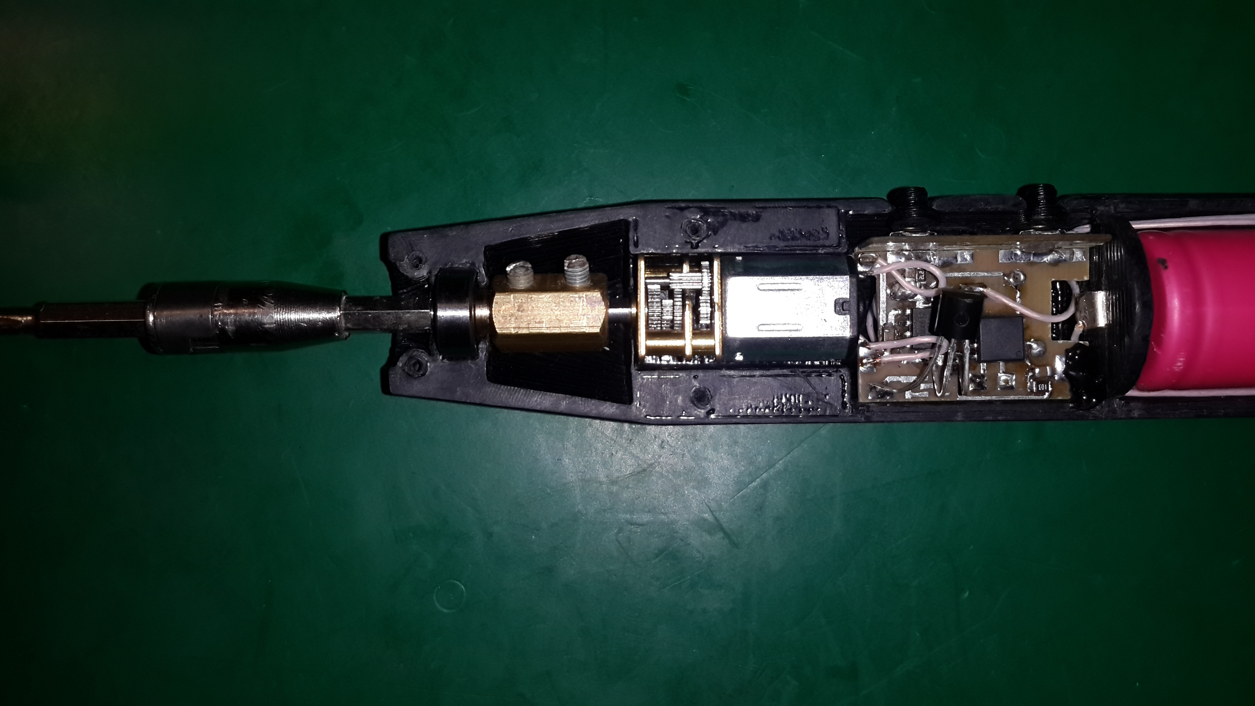
Before you connect all the modules together, you need to install brass contacts in the battery compartment. I took the material for their manufacture from the case of the Ethernet and USB connectors from the motherboard. On the one hand, under the contact, I substituted a small spring, literally a few turns, but this was enough for reliable contact. Now that everything is ready, you can proceed to the connections of the modules. We carry out installation according to the scheme. For mounting I took MGTF, it is very convenient, I pay attention that I used a 0.35 mm wire for minus and motor power, the rest of the communications are made with 0.15 mm wire. For convenience, there are places in the case for laying the wire, after installation it can be fixed with adhesive tape or hot melt. Connect only with battery extended !!! After the installation is completed, we check and carefully observe the polarity of the battery installation, make the appropriate marks on the case or on the masking tape. Insert the battery, check the performance, if something is wrong, then check the components and installation. We install all the boards in their places in the case. The controller board is additionally fixed with black hot melt glue.
Now install the bearing. Then we put the coupling on the motor shaft, but do not tighten the screw, we insert the motor with the coupling into the housing. Insert the bit holder's shank with external moans into the bearing and immediately drive it into the coupling. We tighten the coupling as close as possible to the bearing and tighten both locking screws. It should look like the image below.
Now we insert the remaining pushers for the buttons, close the second half of the housing and screw in with screws. All the device is ready for testing.
After 4 months of operation as the main tool for assembling / disassembling small equipment (laptops, tablets, etc.), the screwdriver showed that the efforts made were not in vain and it deserves to take its place next to the rest of the tool in the workshop. In total, I made 2 copies, one for myself, and the second colleague, because of which it all started, he also has positive feedback. Battery charge on average once a month.
I hope my experience to someone will be interesting or useful, if not for repetition, it may push to their own development.
Thank you all who read to the end!
All schematic and printed circuit board files, as well as model source and print files can be found at github.com and thingiverse.com, but the repositories are still in the works.
By popular demand, the repository has posted the BOM, as well as the Autodesk Inventor models.
1.
www.thingiverse.com/thing : 2746308
2.
github.com/levichevdmitry/electric-screwdriver